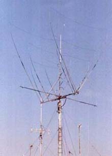
MY ROTARY DIPOLE FOR 30/40 mt
(Click here for drawings)


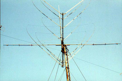
After having built the vertical antenna for 30/40 mt., in consideration of its goods perfomances, I decided to resume  the rotating dipole, already seen at the beginning of this auto-construction. In consideration  of its acceptable proportions, contrary to what expected at the beginning,it was only matter of  adjusting some mechaninal problems connected with robustness under heavy winds.  It was, as a matter of fact, necessary to insulate the first two portions of the half-dipole for 30 mt. in order to mount the linear loads. I then started from the text of the vertical, where the dimensions  of the elements remain more or less the same,  as well as for the linear load for 30 mt.  I then had to solve the problem  of supporting the central portion in which I had to mount the two semi-dipoles.
I decided to use a rectangular aluminium pipe 35 x 50 mm, 150 cm. in length.
On it I then calculated where to drill the holes to mount  the brackets necessary to fix the antenna to a square boom of 40 x 40 mm. which would be then  mounted to the mast.

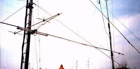
On the rect. pipe I drilled the four holes  in correspondence  of the beginning  of the semi dipole  of the most outside part of the support. These holes  must have a diam. by 17 mm since they must accept the 4 shaped insulators so as the two semi-elements can be acceted inside. You will then  drill the two semi-dipoles, exactly in correspondence  of the four  holes made on the support, with a diam. by 7 mm. and you will then fix the two semi-elements  with four nuts.
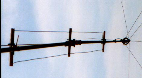
You will then mount  the pipes, already prepared with the relevant linear loads. As far as the attachment of the linear loads is concerned, each of you will do his best to find the most suitable mechanical solution. You will also consider the possibility of lateral vents, at the end of the work. This because when traps for  30 mt. are mounted, plus the tip and the capacitive head for 40 mt. the whole thing will somehow  swing at the ends. One solution could possibly be the one I studied time ago for the vertical, but horizontally and without the necessary result.
I then decided to leave the teflon tubes either inside and outside, according to the original project. I kept on mounting the necesary pipes to complete  the 30 mt. and then I put a vent on each side, the two ends have been fixed at approximately 1 mt. from the center of the dipole. The electrical part differs, from the vertical, because of the presence of a hair-pin by 1.30 mt. long that will be somehow fixed to the neutral point of the boom. At this stage you have only to check  all dimensions as shown on the drawing and try the antenna.
In 30 mt. the passing band is approx. 120 khz, exact on 40 mt.
You will then spend some minutes for necessary adjustments.
At the end I am sure you will be surprised of the results. 

        MODIFICATIONS NECESSARY BEFORE MOUNTING ON THE ROTATOR.

Though the electrical performance of the antenna is acceptable, before
mounting it on the rotator, the first time, it was necessary for me to make some little changes.

Personally  I decided to make it lighter  and more robust and elastic, so I decided to shorten it by 1 mt.
1 - To make it lighter I used two fishing rods, 3 mt. long, eliminating
the thinnest parts, then cutting them at the right dimensions as in
aluminum. For the electrical part, I used  a 1,5 mm. copper wire fixed
to rods with plastic brackets. In the total length of the wire the linear
load is included (same as for the prototype)
2 - In order to shorten the elements by 1 mt. without loosing the original
efficiency, I used a capacitive hat  also for 30 mt. ( 3 radials by 33 cm.
in steel wire of 2 mm. diam.), Then, after the 30 mt. trap, I wound , with
separate turns, 1.20 mt. of enamelled copper wire of 1.5 mm. diam.
This way I reached the right situation for 40 mt. and then used another
capacitive hat for the final setting.(5 radials  by 45 cm.)
With all this I shortened  the semidipole by  1 mt. in comparison with
prototype . So I had the possibility, once installed, to rotate it safely
among all other antennas.


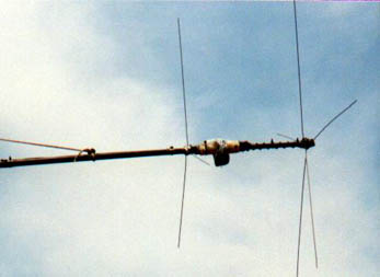
3 - In order to make the whole thing resistant to weather conditions, I put inside each rod a PVC pipe, of different sizes, fixed with screws in order to make it one body  of the outside rod and the inner pipes.
No more problems with wind and snow!
Nothing more to be added. Please consider that this antenna can be
easily  home-made with scrap materials easily to be found.
The pictures show the whole situation with all the aesthetical defects.
PLEASE DO NOT CRITICIZE BEFORE HAVING TRIED IT!
YOUR DX ON 30 AND 40 WILL DO THE REST.
Always at full disposal for any further information.

73, IK4DCS - Franco


ANTENNA's