![]()
![]()
![]()
![]()
![]()
|
|

MODIFICATIONS FOR A DELTA LOOP ANTENNA.
FOREWORD
This is not a theoretical text but the result of many experiences
lived through the action of two heavy wind-storms.
I have no intention to teach anything to anybody, but i would like
to convey some practical suggestions to the users of this type of
antenna so as to avoid a continuous periodical maintenance,usually
at least every two months. The antenna I am talking about is a
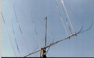
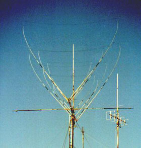
delta loop for HF bands 10/15/20 mt. of commercial Italian make.
It consists of 3+2+2 elements: one radiator and one reflector for
each band and only one beam for the 10 mt. band.
From an electrical point of view, the radiators depend upon separate
feed gamma matches for each band which have three different ends.
As far as the antenna operation is concerned there are no objections
to be made since I am still using it with very good results also on
WARC bands of 12/17 mt.An antenna tuner is necessary but it works!
If the antenna works well, where is the reason of writing these lines?
And here we are.
|
The mechanical aspect can be improved. Because the antenna is fine to
be seen, it works well but nothing is perfect and here I want to give
some suggestions to anybody is going to buy this type of device.
I went through two heavy windstorms in one month.
The first made a lot of danages but after my modifications the second
storm passed without creating any problem.
My antenna has a double craddle boom of 5 mt. with and underlying bracing
the length of which is only half the total length and consisting  of a
square tube with an  outside measurement is 40 mm.

The attachments of the elements to the boom are in solded aluminium with
the classical V shape on a square tube with an inside measurement of 40 mm.
which  allows  the  adjustment of elements at different spacings with some
reinforcing concerning the 20 mt. elements.    Truth to tell, the boom is
drilled for the elements mounts. Under the wind action the problem arises
on  the  elements  and  as  a consequence on the part of boom without the
underlying double craddle reinforcement, exactly where the longest elements
of 20 mt. are. In order to solve the problem of this unbalance under wind
action, in an antenna of this type, you only have to introduce on the parts
of boom,  not already  reinforced  by  the  double  craddle,  a  stiffening
consisting of a tube fitting into the existing boom free from any previous
reinforcement.

Then, on the upper face of the modified boom ends I have mounted two rings
with a 6 mm. diam. and from here a sheathed  steel cable, at 1.20 mt. over
the boom, goes to the mast in order  to support the heaviest and  farthest
elements. Since I have not found anybody  able to alluminium  soldering in
the surroundings I could not extend the double  craddle, since this  could
have been another solution.
Another important aspect to be taken into consideration is the base of the
elements and in particular that of the 15 mt. reflector and the 2o mt. el.
At the joints of elements to the V attachment I have inserted a thicknessing
of adequate diam. just enough to  reach a total thickness of 5 mm.
In my case the elements, at the base, have a  diam. of 25 x 2 mm.  and I put
inside a piece of 20x3 mm. with a length of 40 cm where one side is attached
to the antenna element with self threading 5 mm. screws.  The same operation
is to be made, on the other side, to the V base.
The result of all these operations will be an extremely strong  structure.
No more loosen screws as happened before. No more bending  of elements.
6 mm. bolts could be used instead of screws but there is a risk of deflecting
the aluminium tubes. This could be anyway another solution.
The antenna elements are made in aluminium and the upper part is made with
fiberglass fishing rods with inside the electric wire necessary to complete
the looping.
This is for sure the best part of the antenna. Under the force of heavy winds
the elements  actually twist, bend  and sometimes it seems they are going to
take off (A serious attack to your heart conditions!), but at the end of the
storm they go back exactly where they have to  be as if nothing happened.
But all this is possible only after my treatment.
|
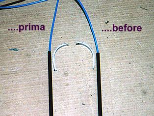
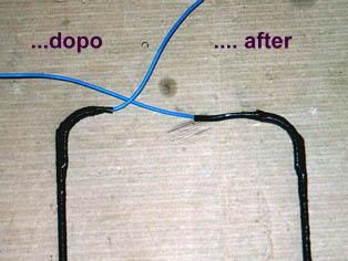
At this stage I must suggest a further modification: where the wire comes out
of the rod,since the wire could accidentally  be cut, I have put a 40 mm. PVC
tube cut in two parts. One part is  mounted at the rod tip and the other will
lead the wire into  a larger bend.   Then the  wire will  be connected to the
one of the loop by insulating tape.
 |
 |
After seeing the results of the first
wind storm I decided to make the modifications. The boom was twisted and I had
to replace it completely. Screws ere loosen and 30% of them missing.
One wire was cut by fretting on the rod tip of the 2o mt. reflector.
Considering the important structure of this type of antenna, I believe it would
be better to make the modifications before problems arise.
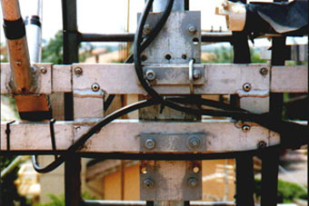
Don't forget to reinforce the attachment of boom to mast.
I used a vertical plate of 350x150x8 mm. making the necessary holes for
brackets which should have a diam. of at least 8 mm.
After all this you may forget any worry about your antenna reducing to
the minimum, if any,the maintenance.
Anybody who is interested may apply to me since I am at full disposal
for any further information.My e-mail address is ik4dcs@libero.it .
Have a nice time and so many DXs.
|
IK4DCS - Franco
|
|
|