|

Scheme
Component
Support MG-2
| |
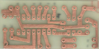
The electric scheme
In the first figure we can observe the electric scheme of the interface
F-bus/M2-bus from me realized for connecting my Nokia 6150 to the PC. Naturally we can
connect other cellular Nokias of the series 5110, 61xx and 7110.
On the left we can notice the pins of the door seriale of the personal computer. When we
realize the cable that you have seen in the preceding pages we have to respect the pin1
correct connection, 2, 3, 4, 5 and 7. Since pin1 and 2 are connected together I have
chosen of to use 1 meter flexible cable to 5 threads rather than to 6. Suggestion to mark
on a sheet the relative pin and color of every thread in way from not to commit errors. In
my case I have: (Red-pin4), (White-pin7), (Black-pin5), (Yellow-pin3), (Green-pin1 and 2).
The cable that will go out of the base of the direct support to the connector NOKIA,
visible to the right of the scheme, it will respect the followings colors: (Black-pin9),
(Yellow-pin6 and 7), (Green-pin8).
In this way can reduce the risk to the least one to commit errors!
When the interface is connected to the PC, the pin4 of the connector female DB9 are found
to a level of around -10V. Under these conditions the diode LED is polarized correctly
therefore it will be illuminated. When we use the software for the connection, pin4 it
will be brought to +5V, the LED will be extinguished and on the display of your NOKIA the
writing Connected " Accessory " will appear. Since the integrated IC2 must have
fed to 3,3V the deriving tensions they are used by the door seriale of the PC. (A big
advantage in how much we don't need external alimentatori). The regulator IC1 stabilize
the tension to +5V while the diodes Shottky D3, D4 and D5 provoke a fall of general
tension of 1,8V. This stratagem allows of to feed the integrated IC2 correctly to the
tension of 3,2V.
The integrated IC2 heart of the interface is a MAX3232, a chip realized by
the Maxim devoted to the management of the signals in gone out of a door RS-232 (our
seriale). These are converts in impulses TTL and viceversa. You can replace it with other
cips of other houses as the serious ADM.
To be able to have the correct tensions related to the logical levels of the door seriale,
the integrated one he has equipped of a converter of tension internally. Thanks to the
presence of the condensers C3, C4, C5 and C6 can get the tensions of -10V for the logical
level 1 (for the door RS-232) and +10V for the logical level 0 (for the door RS-232).
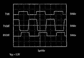
We make an example..... if on the pin 11 apply a logical level 0 (or 0 volts), on the pin
of exit 14 will find again a tension of +10V, if on the pin 11 apply a logical level 1 (or
+2.7 volt), on the pin of exit 14 will find again a tension of -10V. When on the pin
13 have a tension of +10V, on the exit corresponding to the pin 12, will find a logical
level 0 (or 0 volts), when on the pin 13 have a tension of -10V, on the exit corresponding
to the pin 12, will find a logical level 1 (or +2.7 volts). Observe the chart of the
different level logical!
| |
RS-232 |
TTL |
| Logical level 1 |
-10 volts |
+2.7 volts |
| Logical level 0 |
+10 volts |
0 volts |
The diodes D8 and D9 are of the zeners from 2,7V used as protection to avoid that to
the jail cell a signal of more elevated tension comes able to damage it. The JFET, R1, R3
and D6 thanks to the connection at pin4 o'clock (RTR) they manage the signal MBUS. If
desire consultare the Data Sheetses related to this component now take advantage of
it!
Does to avoid of to damage the jail cell check the connections attentively, (memoirs the
colors of the threads of which I have spoken to you in the preceding pages?) and the
operation of the circuit before to use it. Before connecting the interface to the PC
and your Nokia make this test! With a digital tester it selects formality ohm, a ferrule
connect to the pin5 of the door serial while the other ferrule to the pin9 of the
connector Nokia. You will feel the "bip" of your tester that signals continuity.
It now moves the ferrules on the pin2 of the seriale and on the pin8 of the connector
Nokia. It short-circuits with two crocodiles IC2 the pin14 and 11, on the tester you will
have to read 1000 ohms. It moves the ferrules finally on the pin3 of the seriale and on
the pin7 of the connector Nokia. It short-circuits with two crocodiles IC2 the pin13 and
12, on the tester you will have to read 0 ohms, you will feel the "bip" of your
tester that signals continuity.
You now connect the circuit to the personal computer but not to the Nokia, with the
tester, verification the levels of tension on the entry of the regulator IC1 (they have to
be us around 10 / 12V) while on his exit, (opposite pin), they owe 5V to be present. It
now measures the tension on IC2 the pin16 to verify the presence of 3,2 / 3,3V and the
tensions on pin11 and pin12 (always of IC2) to verify the absence of superior tensions at
2,7V o'clock. If everybody the verifications have not underlined problems, it is possible
to connect the jail cell.
I have seen that they circulate less complex schemes that use the integrated MAX232, I
have avoided of to use it in how much this needs a feeding to 5V while the entries of the
NOKIA are not bearing more than 3V. I am favorable to the protections adopted in these
circuits but in case of I spoil the feedings in game they are not reassuring. Think is
worth the punishment to spend some thousand of liras in more to protect a good as the
Nokia 6150 that little doesn't cost!
The connector
In the third figure it is visible the piedinatura of the cellular Nokias
5110, 6110, 6150 and 7110. For the correct operation of the circuit we have to use the
pins 3, 9, 5 for the kit vivavoce and the pins 6, 7, 8 and 9 for the interface. Rhyming
you, for the technical details, to the pages that follow.


|