Apex AD-660 Firmware Switch for multiple EEproms.

I like very much the different releases of firmware that I found on the internet for my AD-660.
In particular I like the SAMPO release that allows me to play MP3 and view JPG, MPG off of a Hard Drive like never before.
On the other hand, I like the original software from APEX because I feel it works better with the remote I have and the front panel.
So, how to have both, or more, systems running without having to open the case and replace SW every time? Here's where you find the answer.

 Let's start by saying that my AD660 has been modified so much I don't think it even looks like an original anymore.


After the original DVD-ROM burned out, I had it replaced with a generic and cheap 10X IDE. That is probably not the best solution of all, but I could not put my hands on the same type unit that was mounted. It works, that's all I care about, even if it's a little (lot) more noisy than the RAITE unit.

Even the mechanical issues were easy to resolve. I had to "glue" the frontal black piece to the beige tray of the drive and use mounting tape to stick the unit to the floor of the cabinet, but so what? You'd never know the difference if you saw it. Besides, the unit "sits" on a shelf, I don't use it as a baskeball.

I added a 13Gb HDD from WD where I stored a whole bunch of my favorite music (that I own on CD) after converting it to MP3. I also stored some of my favorite home video converted to MPG2 and a set of pictures I often show to friends. I like the WD136AA because it's not so power hungry to overload the power supply.
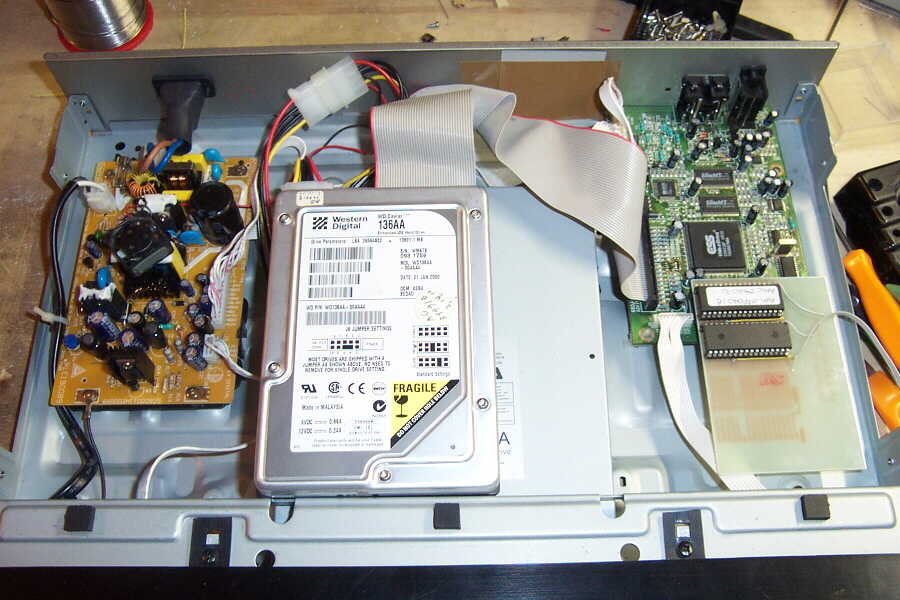
Every other HDD I tried did not work because it would jam the PSU, even the little 2.5" ones. Besides that, it was the only spare drive I had that was big enough to allowed me to put some 6000 songs on it. Of course, to take advantage of the extended IDE capabilities, I needed the SAMPO firmware as opposed to the original APEX one.

Since I'm paranoid, I added a small fan to the Power Supply. Just draw 12VDC from the connector that goes to the HDD and DVD-ROM.
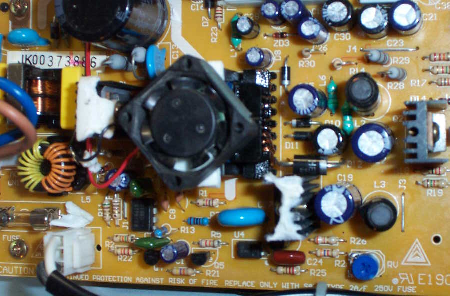
Hey, it's only more juice coming from the PSU that we are cooling down!!! Just kidding, this fan's consuption is nearly nil.
I am lucky enough to own a AD-660 set that carries a standard 32-DIL memory chip, because on the main board there's room for a surface mount chip (PLCC) that would be a little messy to deal with. In that case I would take that chip out of the socket (or just remove it altogether) and add the standard DIL socket instead. The main board can use either one since they are connected pin to pin.

CLICK HERE FOR SCHEMATIC
In GIF format
 The next step was to design a way to swap between two (or more) EEPROM 29F040 so that each one could hold a different version of firmware. The very easiest way would be to piggyback 2 chips, (literally solder them one onto the other!!!) pull out pins 22 from both chips and send them to VCC through a 10K resistor. Then, connect either pin 22 of each chip to pin 22 on the original socket. Sounds hard to do? It's really easy, but kind of kinky, and I would use it only if I had no way to build a PCB at home.


CLICK HERE FOR PCB LAYOUT
in PCX format. Print as 4" X 2.75" @ 240dpi
Works great if printed on high quality transparency film and then used on photo-sensitive boards.
By the way, DO NOT USE a 27C040 directly in place of the 29F040 because they are NOT pin compatible. You would need to re-route a few pins if you wanted to use Eproms instead of Flash, and still the 70ns speed is really important. Even 90ns chips won't work at all. So you would have to buy 27C040 at 45ns.
The easiest way to get my AM29F040-70 was www.mouser.com for about 8$ ea.
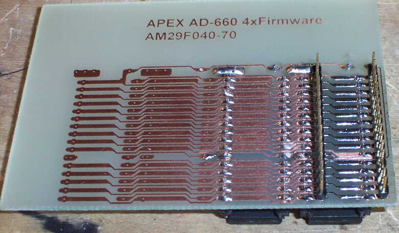
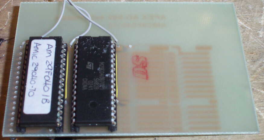
So, instead of piggybacking, you can build a little PCB that will host 2 to 4 chips.
All the lines are paralleled, except for pins 22 that will be used for Chip Selection.
You need to connect pins 22 with wires on the component side like in the picture here.
The 32 golden pins to the far right will plug into the existing socket on the main board. They need to be soldered directly from the solder side of the PCB, so be careful to keep them a little away from it.
If you want to be really kind to your AD660, make sure there are no shorts between any pins.

 
Here's the final product. I only put 2 chips on it, but I can always add 2 more later if I need to.
The wires go to a simple switch that can be mounted on the back of the cabinet.
I WOULD RECOMMEND you DO NOT switch between chips when the unit is ON. God only knows what the CPU will find itself doing if you abruptly jump from one program to another... That's why it's a good idea to put the switch in the back.


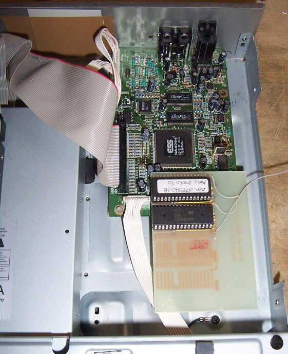
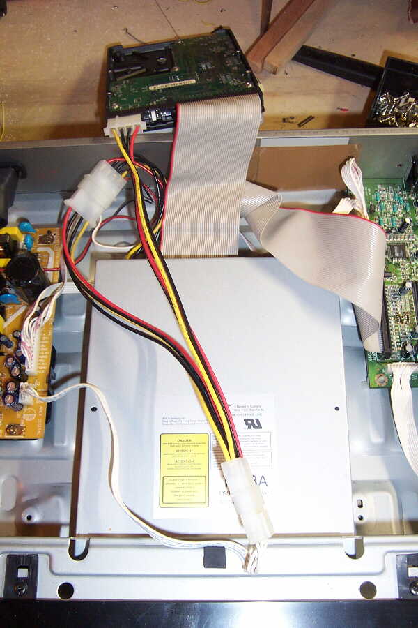
Here's another view of the whole thing.

As you can see, it all fits just fine. When you print the PCB, make sure you leave no room on the side next to the main board so that you don't bump against the connector and capacitors already there.

If you plan to program your chips with a standard programmer, you can leave them on this multiple board and just switch from one to the other before you start writing.

Now, I have to admit there are other ways to achieve the same results without using multiple chips. For instance, you could use a 29F080 or even bigger chips and just work on the extra address lines.
For a 29F080 (1Mx8bit), you would have A19 to connecto to GND or VCC to switch between banks of memory.
On a 29F016 (2Mx8bit) chip you would have A19 and A20 to connect to Dip switches or a binary switch to select one of 4 banks. The only problem with that is that starting from the 29F080 on, these chips are 40pins in size, and so you definetely need to build a PCB to rewire the whole thing. Also, the 70ns speed remains a must and the cost goes up and up.

UPDATE
I went back to the NERD-OUT website to learn about background pictures. So, I put together a couple of images that I really like for my player.
Really handy to record a test pattern in front of tapes or just as a lab signal generator


Works very well with PAL systems because of the layout that overlays to the MP3 and Setup screen

Learning out to modify the firmware also sparked a new thougt. Since I have finally found the release that I really like (631CF for AD-660 dated 8/18/02), I decided to program 2 chips with the same firmware but different background pictures.
This works very well with the firmware switch. it works so well, that I can even hot-swap from one to the other. No need to power off the machine. Using the Setup key I can refresh the screen. I might not be crucial to anybody, but I think it's kind of cool.