uBrain
microBrain (22/04/2002) A POWER SUPPLY FOR CYBERNETIC MODELS
An example of power supply for cybernetic models is the following. It is formed by one rechargeable battery that can be of any type (NiCd, NiMh, Lion) B1, from a solar cell SC1 and from a diode rectifier D3.
From the power supply two testpoints also escape (not marked on the scheme) that they serve to the circuit generating of stimuli of the hunger and the phototropism.
When the light that strikes the solar cell produces a voltage higher than the rechargeable battery, a current flows toward the battery reloading it, when voltage produced from the solar cell is lower then the battery voltage, the diode prevents that the current flows in inverse sense unloading the battery.
The chart that explains the operation of this circuit is the following:
Caso Batt (in) Cell (in) Camina (out) Cerca Luce (out) 1 0 0 1 1 2 1 0 1 0 3 0 1 0 X 4 1 1 1 0 In the fields Cell and Batt symbol 0 (zero) means "low voltage level", the symbol 1 (one) means "enough voltage level" (battery charged).
In the fields Cammina (walk) and Cerca Luce (find light) the symbol 1 (one) means "walk" and "follow the light" (positive tropism), the symbol 0 (zero) means "stop walk" and "stay away from light".
This give to cybernetic model to have four behaviour imposed by the necessity to feed on.
The second condition (Caso) represent the normal life where the model is satiated (full charged battery) and then can walk without necessity to find food (light). On the contrary it go away from light.
This condition will be followed by first condition (1) where the battery is partially discharged and there isn't enough food (light), so the model walk to find food and do it with a positive tropism. In this case it will find the light to recharge batteries.
Sooner or later (we hope :) it will go in the 3rd condition where there is a lot of food (light) and then it will stop to recharge the batteries. In this case the tropism it's not important because it is stationary and it will stay in this condition until it will be satiated or the light will go off.
When the battery will be full the model will go in the 4th condition and it will go in the normal life (walking) and will go away from light (negative tropism).
We can write boolean equations:
____ _
Walk(Cell,Batt) = Cell + Batt Y(A,B) = A+B
____ _
Tropism(Cell,Batt) = Batt Y(A,B) = B
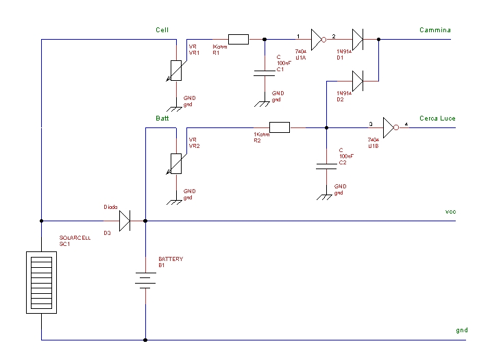
And then we can design the schematic:

The two trimmer VR1 and VR2 need to modify the operational threshold. We can notice that this circuit need to be modified if the battery have a voltage higher than 6 volts that is over the possibilities of TTL circuits working at 5.5V maximum.
It's obvious that the threshold circuits are not so accurate and in some case the outputs could seems not logical.
To come to the conclusion we can say that this solar power supply include a low level logic that simulate an instinct needed to survive, consisted of two neurons (Nu type) and a phantom OR.
Here the complete schematic.
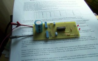
... and the photo of prototype under test.
Obviously we can substitute the solar supply with others (wind, dc socket and so on).
Intentionally I haven't used an OR (7432) instead of two diodes to save an i.c.
P.S. The big cap visible in the photo is needed to simulate the battery to do a short charge test.
Instead of 7404 we can use 7414 that works better.