Fundamentals
Of Fibres
The
fundamental principle that makes optical fibres possible is total internal
reflection. This is described using the ray model of light (see figure 1).
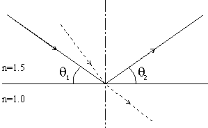
Figure 1
- Total Internal Reflection
From
Snell’s Law we find that refraction (as shown by the dashed line) can only
occur when the angle theta1 (between the incident ray and the material
boundary) is large enough. This implies that as the angle is reduced, there
must be a point when the light ray is reflected, where theta1 = theta2 (note
that this is only true when the refractive index of the initial medium is
greater than that of the adjacent medium, as shown by the value of n on the
diagram). The angle where this happens is known as the critical angle and is:
![]()
In fibres,
there are two significant sections – the core and the cladding. The core is
(according to the ray model) where the light rays travel and the cladding is a
similar material of slightly lower refractive index to cause total internal
reflection. Usually both sections are fabricated from silica (glass). The light
within the fibre is then continuously totally internally reflected along the
waveguide.
When light
enters the fibre we must also consider refraction at the interface of the air
and the fibre core. The difference in refractive index causes refraction of the
ray as it enters the fibre, allowing rays to enter the fibre at an angle
greater than the angle allowed within the fibre (see figure 2).
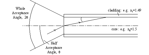
Figure 2
- Acceptance Angle
This
acceptance angle, theta, is a crucial parameter for fibre and system designers.
More widely recognised is the parameter NA (Numerical Aperture) which is
given by the following equation:
![]()
Also crucial
to understanding fibres is the principle of modes. A more in-depth analysis of
the propagation of light along an optical fibre requires the light to be
treated as an electromagnetic wave (rather that as a ray). Unfortunately there
is not room for such a mathematical treatment in this essay, but we should note
that it leads to a quantisation of the ‘angles’ at which ‘rays’ can travel
through the fibre.
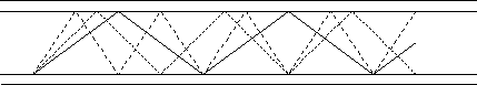
Figure 3
- Modes
The solid
line is the lowest order mode shown on figure 3. It is clear that according to
the ray model the lowest order mode will travel down a given length of fibre
quicker than the others. The electromagnetic field model predicts the opposite
– that the highest order mode will travel quicker.
However, the overall effect is still the same – if a signal is sent down the
fibre as several modes then as it travels along the fibre the pulse will spread
out (this process is known as modal dispersion); this can lead to the
pulses merging and becoming indistinguishable.
One
further classification of rays can be made; meridional
rays pass through the fibre axis; skew rays (hybrid rays)
constantly rotate without passing through the fibre axis.
One other
significant point should be noted from the electromagnetic field model – the evanescent
field. The model predicts that the EM field does not suddenly drop to zero
at the core-cladding boundary – it instead decays as a negative exponential
within the cladding (see figure 4). This is crucial for
various technologies relating to fibres.
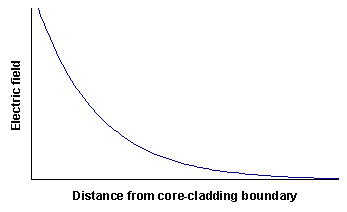
Figure 4
- The Electric Field Within The Fibre Cladding
This
method of signal transmission has benefits in terms of security – for the
signal to be ‘tapped’ the fibre must be broken (since effectively no energy
escapes from the fibre) and this can easily be detected (when no signal reaches
the other end of the fibre!). This is one of the many advantages of the medium.