If there is a need to feed very low power devices you may
resort to infrared optocouplers, solar cells, batteries or low power
transformers although the latter might be rather oversized for the
intended purpose. Eventually, with the exception of solar cells, all
of them draw power from the mains so it might be convenient to use a
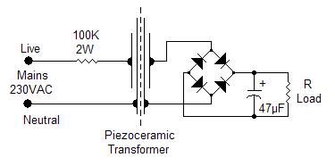
piezoelectric transformer if the power required is in the range 0.1 to
0.3 mW. The schematic shows an easy implementation of such a
transformer.Two
piezoceramic sounders are glued back-to-back so that the mechanical
movement of the first, the primary, is transferred to the second, the
secondary. The ac output voltage can be used as it is or rectified in
order to feed micropower electronic equipment or trickle charge small
backup batteries. The actual implementation requires two
ceramic sounders with high intrinsic capacitance: sounders with 80 to
110nF are readily available and usually come as 50mm discs. Two of
these discs are cut down to 35mm in order to have a more compact unit
and a lower stray capacitance between primary and secondary. A layer
of double-sided adhesive tape is laid on the larger plate of each
sounder in order to assure proper electrical insulation between
primary and secondary. The sides of the sounders are then pressed
against each other and the transformer is ready to operate.
R
Load
VAC
VDC
100 Kohm
5.1
4.67
47 Kohm
4.22
3.29
22 Kohm
2.77
2.06
10 Kohm
1.41
1.1
4.7 Kohm
0.68
0.56
The table shows the measured output under
several loading conditions: the ac output was measured with the load
directly across the output terminals while the dc output was measured
with a full wave rectifier in place.The measured dc voltage refers to a schottky
bridge rectifier but the use of standard 1N4004 diodes will only show
a modest 6-8% voltage decrease. Measurements were taken
with the transformer operating in free air, without any holder, but a
proper mechanical layout would require the transformer to be firmly
held by the edge of the disc. The use of a plastic box is mandatory
for safety reason and improves the transfer of mechanical energy to
the secondary thus obtaining a 15-20% voltage increase.
The principle of operation of a car
hooter has been applied to both a ceramic sounder and a loudspeaker. A
break in the supply current is caused by the vibration of the ceramic
sounder plate or the speaker membrane. You could implement similar
circuits even without a transformer but the voltage range will be
limited, there will be too much sparking at the contact point and
pressure and position of the contact become critical. The transformer
introduces a feedback mechanism thus eliminating or drastically
reducing all mentioned negative effects. An output transformer is used
in both circuits: one of the winding is normally 4 or 8Ω
while the other is at a higher impedance. The larger plate of the
piezomechanic oscillator goes to positive through the contact,
typically an adjustable screw, and the transformer low impedance
winding. To get the correct phase relationship you may need to reverse
one of the windings.A
similar transformer is used for the electromechanic oscillator with
the low impedance winding connected to the speaker. Also in this case
you may need to reverse one of the windings but first you must make
sure that the speaker cone goes forward when the voltage is applied:
reverse the speaker connections if necessary. A small copper strip is
glued on the back of the speaker membrane with a screw placed in the
speaker casing so that it just touches the copper strip.
Frequency of operation is from 1 to 1.5
KHz for both oscillators. The frequency for the electromechanic
oscillator depends mainly on the speaker damping factor: best results
are obtained with the speaker laid against a flat surface or sealing
the front side with a wooden panel.Operation below 0.4-0.6V depends on the careful adjustment of
the screw and mechanical precision of the assembly.
10A
CAR BATTERY CHARGER
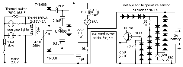
The charger
is suitable for lead-acid car batteries and it is assembled in two
units: a metal box with the toroidal transformer, instrument, lights,
etc, and a small plastic box housing the voltage and temperature
circuit. Connection between main box and sensor is realized with a
standard 3 core x 1mm, electric cable, 4m long. Its resistance is
factored in the circuit calculations and it is the limiting resistor
against overcurrent. Do not change type or length as it may alter the
overall performance and safety of the charger. The sensor box is
typically positioned close to the battery to be charged and two short
flexible leads, 2mm section, 30cm long, one red and black the other,
terminated with good quality clamps make up the connection from the
sensor to the battery.
This solution assures that the battery is charged up to the
correct voltage which depends, in turn, upon the ambient temperature.
The final voltage should be set, with the 200?
multiturn pot, at 14.8V at 20°C-68°F and derated +/-30mV/°C (17mV/°F) at
any other temperature. For example, if the prevailing ambient
temperature is 10°C then the final voltage should be set at 15.1V, if
the prevailing ambient temperature is 30°C the final voltage is 14.5V
and so on. Once set, the circuit will automatically adjust the voltage
to within 1°C. You have to connect a battery in order to carry out this
setting.
A thermistor would have simplified the circuit but its
correct implementation is not easy and it was preferred to employ a
number of diodes. A red led in the sensor box gives an indication of the
correct connection to the battery. However the circuit is quite tolerant
to mistakes: shorting the output will do no arm as there is no voltage
at the output terminals, not until you connect it to the battery. It is
the battery voltage that triggers the circuit into operation and once it
is disconnected from the battery the voltage too disappears from the
output. Only if the battery voltage is above 7-8V then the circuit will
operate. A reverse connection of any battery will do no arm either as
the circuit will simply not operate. It will withstand a temporary
connection of a 24V battery; above this voltage the input circuit is
overloaded and could be damaged.
Current control is achieved by switching the SCRs at the
appropriate time through the BF761 collector current. The blue led, but
any other colour will do, gives an indication that the unit is charging
the battery. The led will start flickering at the end of the charging
cycle so you know at a glance that the charge is coming to an end. You
may leave the battery connected after it has fully charged as there will
be a trickle charge which will keep the voltage at its optimum level.
Switching noise is eliminated by the 85μH
choke made up by winding 27 turns of 1mm enamelled wire on a ferrite
ring 27x11mm. Due to the way SCRs operate, the common line is positive
and not negative as one would expect. Care must be exercised when
connecting all the polarity sensitive devices.
A toroidal transformer has many advantages: it is small,
highly efficient, will tolerate a moderate overload and will consume
little power, only 3.5VA when switched on and no battery connected.
Cost, at this power range, is surprisingly close to a traditional
transformer, yet, the inrush current when switched on can be so high,
depending on the exact time with respect to the mains sinewave, that the
collapse of the ensuing strong magnetic field will produce mighty spikes
up to 500V at the secondary, destroying whatever they find in their
path. A few capacitors, the use of fast diodes UF4006 and the high
voltage transistor BF761 take care of the problem. The main switch
should be rated at 10A.
SCRs can get rather hot; the best solution is to mount them
on the metal case itself using appropriate insulating kits. As a
consequence the box will warm up especially at the beginning of the
charging cycle when the unit may be temporarily overloaded. A thermal
switch is provided to cut out the mains supply under extreme temperature
and overload conditions. This switch is mounted at about 6-8cm away from
the SCRs so that it will take care of the heat coming from other sources
as well, such as the transformer and the choke.
The unit has been tested with batteries from 44 to 100Ah
for over a year, from 0 to 38°C (32 to 100°F); the upper temperature
limit caused the thermal switch to operate. I should relocate the
thermal switch in a cooler place if the designed max operating
temperature of 40°C-104°F is to be met. You may have different
temperature limits depending on the mechanical configuration of the box
and internal components layout. Pay attention to the fact that this
charger behaves like a fast charger for the smaller batteries and
precautions should be taken concerning gas production and it is good
practice to disconnect the battery from the car before charging it.
SIMPLE
WARNING SIGNAL
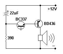
This power
audio oscillator could be used as a warning signal for alarm systems or
to attract attention if something is wrong with an equipment. The
oscillator, about 750Hz, exploits the characteristic of certain NPN
transistors, in this case a BC337, to oscillate if reverse biased and
with the base open. Other equivalent transistors might not work. Despite
its simplicity the circuit is quite flexible: the 390Ω
resistor, normally connected to negative could be switched in through a
logic circuit, so it can be driven directly by the circuit to be
monitored; the base is normally not used but frequency modulation of the
circuit is possible by connecting a modulating signal to the base via a
high value resistor, typically 2.2MΩ.
A 3W loudspeaker is adequate for the circuit and it can be
either an 8 or 4Ω loudspeaker,
although in the latter case a small heatsink is necessary for the BD436.
Peak current for an 8Ω loudspeaker
can be as high as 1.2A but because the duty cycle is relatively small,
the average current was measured at 0.2A hence the overall power
requirement is only 2.4W despite the high volume the circuit is capable
of. The feed line must be well filtered and can be anything between 9
and 15V although adjustment of the resistor might be required as the
oscillation frequency is sensitive to the supply voltage.
Since a new electricity meter, the electronic variety, was
installed at my place, I get cut off if I exceed the set power level,
3.3KWh in my case.
The new meter is unforgiving and although
there is a little tolerance built in, you really never know when it has
gone over the cut off limit, given the number of electric appliances
which are continuously switched on and off.
The circuit was designed to give an
audible warning when the 3.3KWh limit is exceeded. The transformer is a
disused transformer from a soldering gun. It is relatively easy to
remove the few turns of the secondary winding and rewind two turns of
thick wire, as thick as the wire coming from the meter at least. One
turn should be enough if you have a limit of 6.6KWh, but operation at
this power level was not tested. As an alternative you may try a small
toroidal mains transformer: it is easy to add a few turns of thick wire.
Ignore all other windings, if any, except the primary winding, which in
our circuit becomes the secondary winding. The circuit is to be
installed between the electricity meter with its breaker and the house
wiring. With the given components, the circuit will oscillate at 1 sec.
on and 1 sec. off, depending on the load. Adjust the potentiometer so
that there is no sound below the power limit. The varistor is necessary
in case there is a short in the house wiring: the extra voltage at the
secondary may damage the circuit. The piezo buzzer can even be placed
away from the circuit in any place where it can be easily heard.
It goes without saying that you must know
what you are doing as working with the household mains can be dangerous
and remember to switch off the mains breaker before doing any work on
the electric wiring. Do not attempt to install this circuit if you have
doubts on its operation, connections and relevant safety measures.
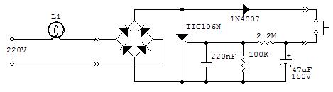
Occasionally you might have a need to keep a light on for a
certain time, usually a few minutes, and be sure that it switches off
even if you forget to turn off the switch. This could be useful in a
cellar or in a closet. The circuit will switch on a light bulb simply by
pressing the push button. After a time of 3-7 minutes it will switch off
automatically. The long delay is achieved by partly using the leakage
current between anode and gate of the scr. This current is dependent
almost on anything: voltage, temperature, lamp power, scr device, etc.,
this is the reason why the timing is not constant but for the intended
application it is not important. If the delay is too short you may
increase the 220nF capacitor up to 470nF. Too high a value will keep the
light always on. It will work with incandescent light bulbs only. its
operation with electronic lamps is erratic and the delay is only 1 or 2
minutes. The scr must be the sensitive gate type and no other type was
tested except the TIC106N.
The circuit is rather small and could be
housed in the same case as the push button, if there is enough room. Of
course you have to substitute the standard switch with a push button.
Operation with a 110Vac mains has not been tested although I expect that
a 100μF 100V capacitor instead of
the 47μF capacitor should do the
trick.
It goes without saying that you must know
what you are doing as working with the household mains can be dangerous
and remember to switch off the mains breaker before doing any work on
the electric wiring. Do not attempt to install this circuit if you have
doubts on its operation, connections and relevant safety measures.
These circuits follow a similar one shown in a previous page but
operate at 5V, and down to 2V (1.5V for the circuit with the
transformer), and it is also louder. To set them properly start with the
trimmer at its highest resistance, connect the 5V supply and slowly
adjust the trimmer until oscillation sets in. Oscillation frequency can
be adjusted, within limits, using the same trimmer. The loudspeaker must
not have a DC resistance bigger than 5.5 ohm or else the higher damping
factor will prevent the scr from switching off and it will latch on
forever. This means that you cannot use a speaker too small,
less than 2 inch diameter. For the same reason it is proper not to use
any electrolytic capacitor. If, while setting it up, you find that the
scr has latched in the on state, temporarely remove the supply voltage
or temporarely make a short between anode and catode. In order to
operate it at 12V you must change the resistor from 82 to 120 ohm and
the trimmer from 1k to 2.2k with an additional 1Kohm resistor in series.
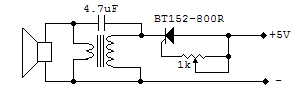
The circuit on the right uses an output transformer,
admittedly not readily available nowadays but was common on old
transistor radios and amplifiers some years ago. Operation and setting
is similar but you may need to invert the secondary winding in order to
have a better stability corresponding to a lower oscillation frequency.
In this last circuit it might be possible to use a low esr electrolytic
capacitor instead of the standard capacitor. If the voltage is increased
beyond 5V pay attention to the maximum current flowing through the
components, would the scr
latch on. Other scr types should work well even if you might be required
to adjust the trimmer value.
Here
we offer some circuit configurations for night lights, other
similar schematics are easily available from the web.
In these circuits we have used a plastic case from some old night
lights: the neon bulb and relative resistor have been removed to
make room for the circuits shown on the left. The first circuit
has 4 leds of any color, although the white ones seem to be the
best option. Power consumption is about 270mW. Please pay close
attention to the leds connection: if you make a mistake in
connecting just one of them, then all of them will blow up on the
spot. The only critical component is the line capacitor, 220nF,
which must be properly rated for the mains voltage, at least 400V. The resistor in parallel
with the capacitor has the purpose to discharge it in a relatively
short time
to avoid any electric shock if
the plug pins are touched soon after it is removed from the
relevant socket. This resistor is not
required if the circuit is permanently wired to the mains and
there is no chance to touch the connecting pins. The 47nF
capacitor, together with the 560 ohm resistor is used to protect
the leds against voltage spikes due to lightning,
switching operations of highly inductive loads on the same supply
line
or simply due to the connection of the night light in the relevant
socket.
All resistors are 1/4 or 1/2 W
and the voltage rating for the 47nF capacitor is 50-100V. Perhaps the only drawback of
this circuit is that there is too much light emanating from it; During
the night our eyes are
accustomed to darkness and this circuit might be too bright for
our taste and it is therefore most suited to light up a large area
rather than a single room. 5mm, clear type leds were used in all
these circuit.
The
second
circuit is a less powerful version with two leds only and really
meager power consumption, just 11mW. This version is the one
which more closely matches the concept of night light: low power,
not a blinding light but enough for our purpose and a limited cost
to build.
The third
circuit is a combination of the others and it is housed in a case
that comes complete with a switch; in fact, some commercially
available night lights have a switch to activate or deactivate
them and here
we use the switch to choose between two power levels: a weak one
and a more powerful one.
Power
consumption is 15mW with the low power setting, open switch, and 310mW with
the high power setting, closed switch. The power rating of
commercially available night lights is between 0.6 and 1W while
the old fashioned type with the little neon bulb is between 0.21
and 0.33W.
In this third circuit we used colored leds: the resulting effect
is pleasant because the room is bathed in a light close to a white
light but the source is colored.
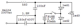
In the
fourth circuit, a very small 80mAh NiMh battery was added. Several
tests were carried out to find the best matching among the charging
current, led color, number of battery elements, two in our circuit,
and the time the green led is shinining when there is no mains.
Normally, closed switch, the NiMH battery is charging while the green
led will avoid any overcharging effect. The switch comes handy when
you do not use the night light thus avoiding the battery
discharge. If you wish, the green
led can be exchanged with the blue led or you may use white leds for
all three of them with the advantage of a longer illumination time
when there is no mains. A very nice color combination is to replace
the red led with a yellow one and the green led with a white one. Only
three leds were used in this circuit. This was necessary to reduce the
excessive reverse voltage across the red led. Power consumption is
around 140mW. Please note that the forward voltage of the green led
will ultimately set the battery voltage. This means that other green
leds might give a slight different battery voltage. The one used in
this circuit would set the battery voltage at 2.78V. This voltage
becomes 2.8V with a blue led and 2.82V when white leds are used. With
no mains, we have a range of three days for the circuit with the white
led connected to the battery and about two days with the green led and
one day with the blue led. The light will go on for twice or three
times longer with ever decreasing output.The light intensity is
minimal but it is sufficient in complete darkness. Remember that NiMh
batteries have to go through 3 or 4 charge-discharge cycles in order
to get the best efficiency. The last circuit is a classic
diagram with bridge rectifier (800V, 1A) and a higher capacity battery. Eventually
this is the circuit I adopted for my purposes. I liked the colour
combination with the blue light when there is no mains.
The circuits operate from a 230Vac mains
but they can be scaled to work from a 110-115Vac mains by doubling
the capacitors value and halving the resistors value and voltage
rating.
It goes without saying that you must know what you are doing
as working with the household mains can be dangerous. Do not attempt to
build this circuit if you have doubts on its operation, connections and
relevant safety measures.
The solar cell is always feeding the Lithium
rechargeable battery and if the voltage goes over a given threshold, about
3.8V, then the white leds will switch on. The same leds, 4 of them, are
used to protect the battery from overcharging. All leds will switch off
when the battery voltage goes below 2.8V and they will switch on again
when the battery voltage is again 3.8V. The on and off voltages become 3.9
e 2.9V respectively at freezing temperatures. The circuit was designed for
the highest efficiency with a current drain of less than 1µA,
with leds off.
Instead of lithium accumulator, you can try NiMh batteries, three cells in
series will give the right voltage and will give more flexibility: if, for
example, the circuit has one only white led, then you need a smaller
600-700 mAh NiMh battery. Also the solar cell must be designed to give a
maximum output of 25mA. The drawback of using NiMh batteries is that they
do not work very well at freezing temperatures.
 If there is a need to feed very low power devices you may
resort to infrared optocouplers, solar cells, batteries or low power
transformers although the latter might be rather oversized for the
intended purpose. Eventually, with the exception of solar cells, all
of them draw power from the mains so it might be convenient to use a
piezoelectric transformer if the power required is in the range 0.1 to
0.3 mW. The schematic shows an easy implementation of such a
transformer.
If there is a need to feed very low power devices you may
resort to infrared optocouplers, solar cells, batteries or low power
transformers although the latter might be rather oversized for the
intended purpose. Eventually, with the exception of solar cells, all
of them draw power from the mains so it might be convenient to use a
piezoelectric transformer if the power required is in the range 0.1 to
0.3 mW. The schematic shows an easy implementation of such a
transformer.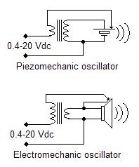
 O
O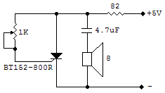
 T
T


 The last circuit is a classic
diagram with bridge rectifier
The last circuit is a classic
diagram with bridge rectifier 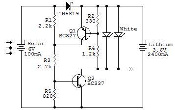 The solar cell is always feeding the Lithium
rechargeable battery and if the voltage goes over a given threshold, about
3.8V, then the white leds will switch on. The same leds, 4 of them, are
used to protect the battery from overcharging. All leds will switch off
when the battery voltage goes below 2.8V and they will switch on again
when the battery voltage is again 3.8V. The on and off voltages become 3.9
e 2.9V respectively at freezing temperatures. The circuit was designed for
the highest efficiency with a current drain of less than 1µA,
with leds off.
The solar cell is always feeding the Lithium
rechargeable battery and if the voltage goes over a given threshold, about
3.8V, then the white leds will switch on. The same leds, 4 of them, are
used to protect the battery from overcharging. All leds will switch off
when the battery voltage goes below 2.8V and they will switch on again
when the battery voltage is again 3.8V. The on and off voltages become 3.9
e 2.9V respectively at freezing temperatures. The circuit was designed for
the highest efficiency with a current drain of less than 1µA,
with leds off.
