- LM317 variable power supply
- Car-Battery charger for Nokia 8210
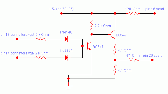
- Vga to tv Converter
- Phone in use indicator
- 1300 Mhz Frequencymeter with prescaler
- Gate Deep Oscillator
- JDM Pic and EEPROM programmer
- Smt desoldering station
- Six channel IR remote system with micro PIC 16F84
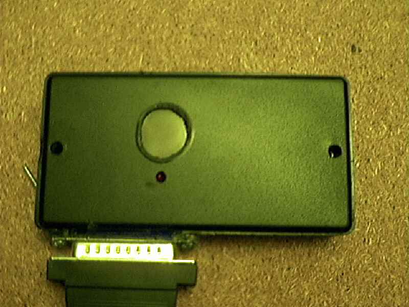
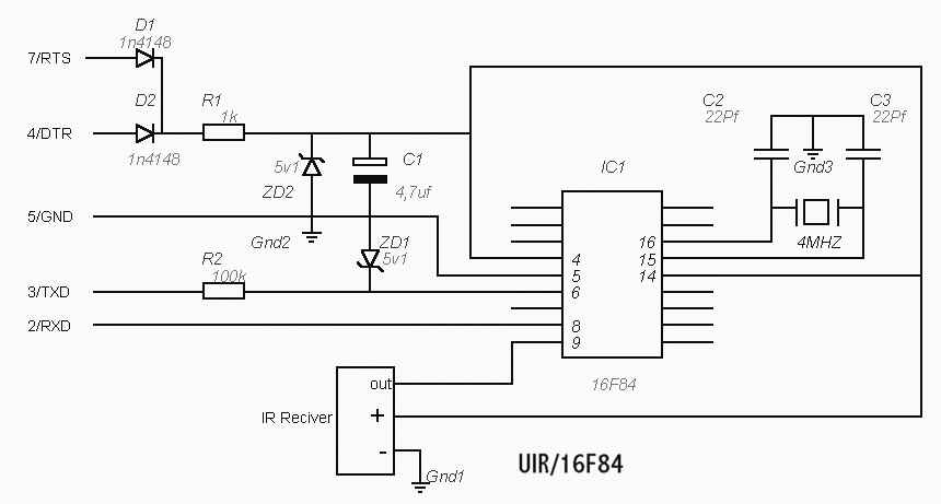
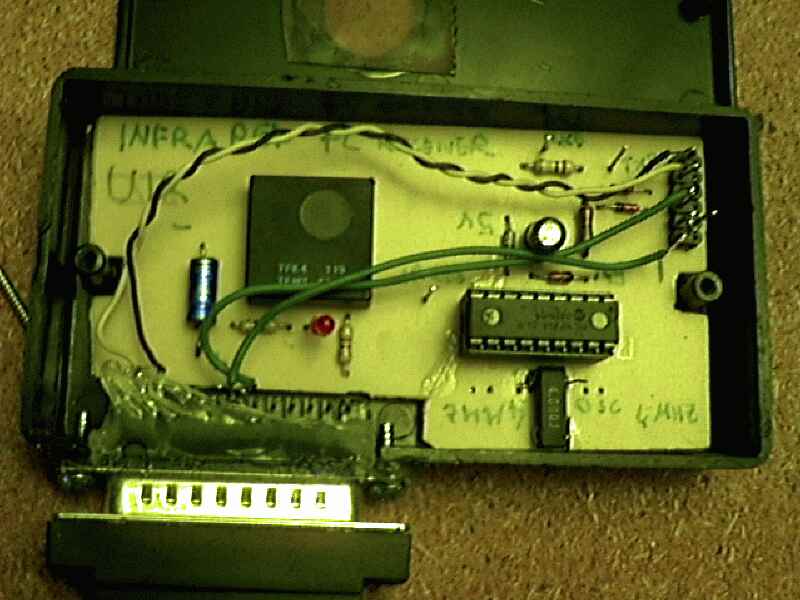
- Universal Infrared Receiver
- Phone amplifier
Visit also my download pages for the Pic code list and the software to use with my circuits.
| Disclaimer: Any illegal use of informations and ideas shown in these pages is punished by the law of your country, I decline any responsibility for the illegal use o these pages and for the damages that them should cause to anyone or to anything. Use it at your own risk |
|
It's a variable power supply
based on a lm317 voltage regulator the range of power is between 1.6 and
13.5 volt, you can get till 1,5 Amp. if supply the IC of a good cooler
such as an aluminium plate. The range can be varied by turning the 1k
linear potentiometer. This circuit is good for that kind of little home
appliances like walkman, disc player, gsmcharger. Obviously the transformer should be adequated to the current requested from the circuit ! |
![]()
|
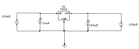
It's just a simple power supply with a 7805 regulator, the chip must be mounted on a large metal radiator, because the current requested by the regulator is near 0.4 A. However to lower the power, you can put a 10 ohm 2 watt( 0.4*5=2 w) in series to input pin. You can use it in you car , by connecting it to your lighter plug. A simple and functional project for your Nokia 8210. The charging time is equal to that of the standard charger.
|
|
Here are two schematic taken
from Tomi ENGDAHL and the software under windows |
|
To use the circuit you need this software |
![]()
|
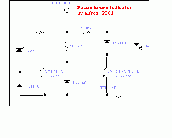
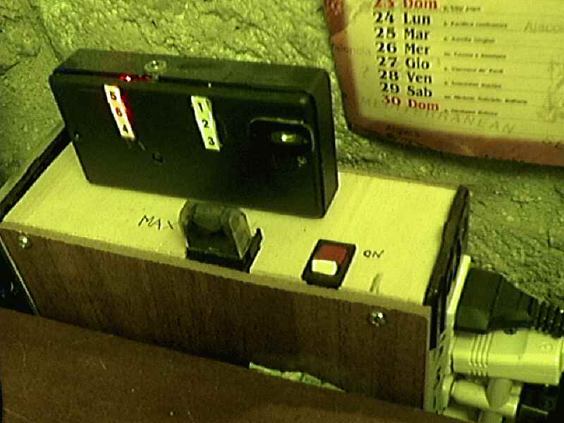
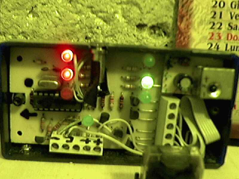
This circuit is useful to show chen your line is busy. I used for this a pair of smt transistor, the leds on when the voltage drop down to 40 v. |
|
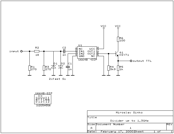
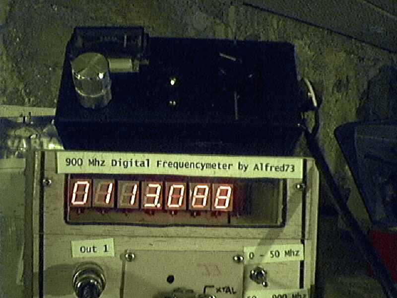
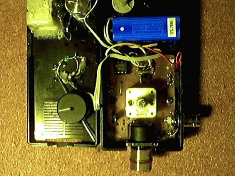
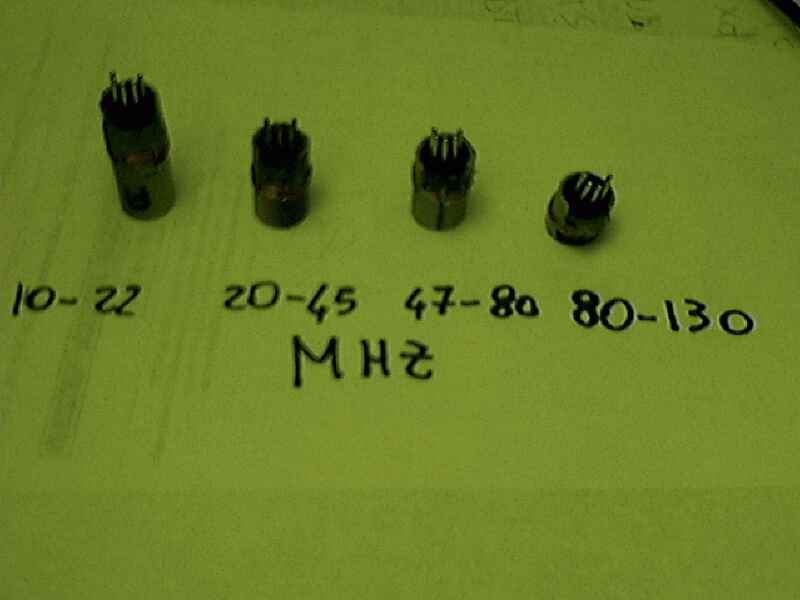
Having found an u664b prescaler chip (Telefunken) from an old tv-tuner , I decided to build a valid frequency counter using pic16f84 , the prescaler I use is able to divide by 64 every frequency from 30 to 1300 MHZ. The original project is from Peter Halicky but as he used a sab6456 prescaler (divider by 256) I had to change the code to adjust the gating time to my different divider factor ( 64) and also to my 4.8 MHZ xtal (he use 10 MHz xtal). However the U664b is perfectly compatible to SAB6456 so you can substitute it pin to pin. The measuring is divided into 2 ranges 0-50 MHZ , 50-1300 MHZ turning a switch.I used for this a 2 way relays to switch between the 2 input port (low MHZ and prescaler). Besides he use a 74hc137 (bcd to decimal converter) to control in multiplex mode the common cathode display , but AS I've no availability for this chip I replaced it with 74 hc138 , slightly different but in this application is fully compatible pin to pin. If you don't have the prescaler you can built it to use the lower frequency range 0-50 MHZ. Inside the code you'll find the formula to modify the timing parameters for your Xtal and prescaler-divider-factor. Consider that those value inside my code are referred to 4.8 MHZ xtal and : 64 prescaler factor.So FINALLY it is a cheap and useful project for those of you interested in radiofrequency. if you need help , write to me , and I'll answer you as soon as possible ! P.S. the software code is free for private use , contact Peter Halicky for other use. For more look at Peter halicky home page : |

|
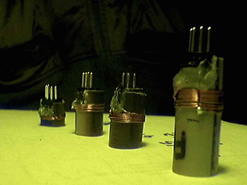
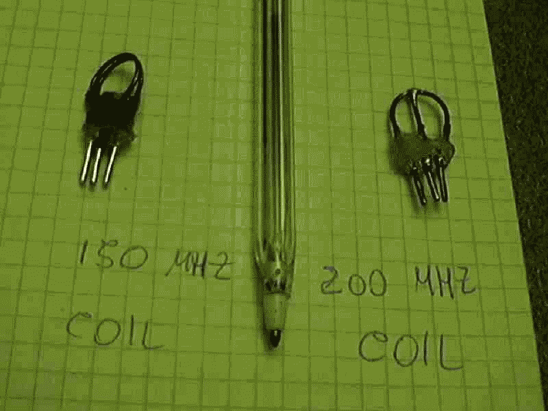
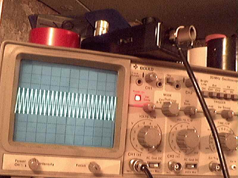
It's just a variable oscillator based on a bf245 or k 161 fet. By changing the coil it can generate frequency between 0.5 and 300 MHZ. this circuit is useful to test radio circuit such as filter, receiver, transmitter and so on . It can be use for coil tuning thanks to the 100microA meter .It must be placed in a metal case but I've used a double sided vetronite board, one for ground. To build it , is requested particular experience in radio-frequency assembling . First of all remember to put as short as possible all connections or you'll have problems over 50 MHZ. .Coils are build as shown later using a 5 pins DIN plug . The central pin is used for central tap of coil . The variable condenser is that used in normal fm-am radio which as 20+20 and 300+300 pF capacitance. The first channel is used for frequency over 50 MHz, the second for the other low frequencies. In my project there is also a little 1 kHz oscillator based on a 555 timer, used to modulate the radiofrequency with an audio signal, useful to test receivers' audio stages. The signal is readable by a medium-sensitivity frequency counter such as that published in these pages. Coil specs:
Obviously the final frequency can really differently from that described above, you will' have to change spacing and add-subtract coil to reach the exact frequency you want by using a counter of a wide band receiver. Remember the first rule on radiofrequency connections : " AS SHORT AS POSSIBLE !!!!!" In the gallery section you'll find some photos about my own GDO under testing. For Information visit this interesting site about GDO schematics : www.qsl.net/iz7ath |
 |
 |
 |
 |
 |
 |
 |
 |
 |
|
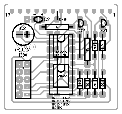
This is a JENS MADSEN 'S project I've built to program my pic and EEPROM (16xXXX AND 12CXXX AND 24CXX) I use it with ic-prog , it is little ,simply to build ,cheap and give few bugs, When I built it , At first it seems not to work properly (read but not write) then I made the following mod to the schematic: added a 1 k resistor in series on rts line and now everything is ok.! |


|
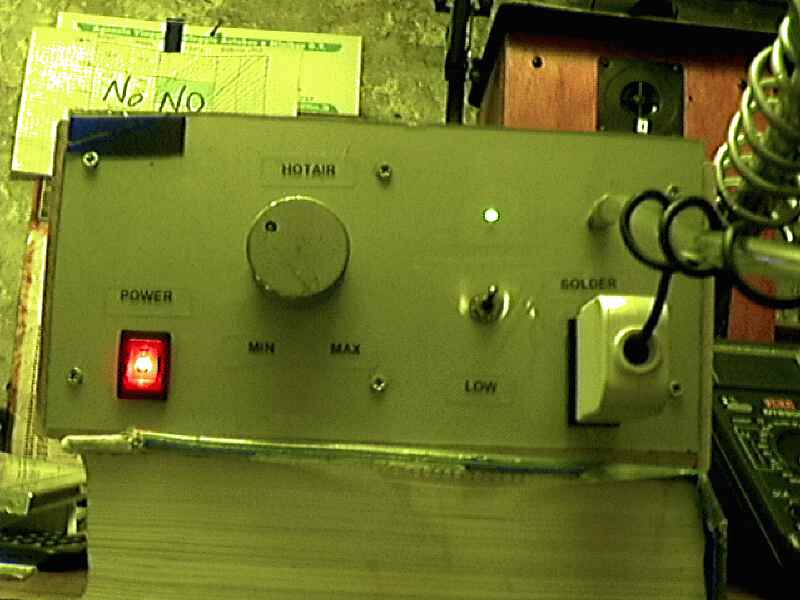
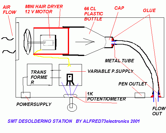
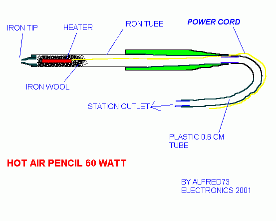
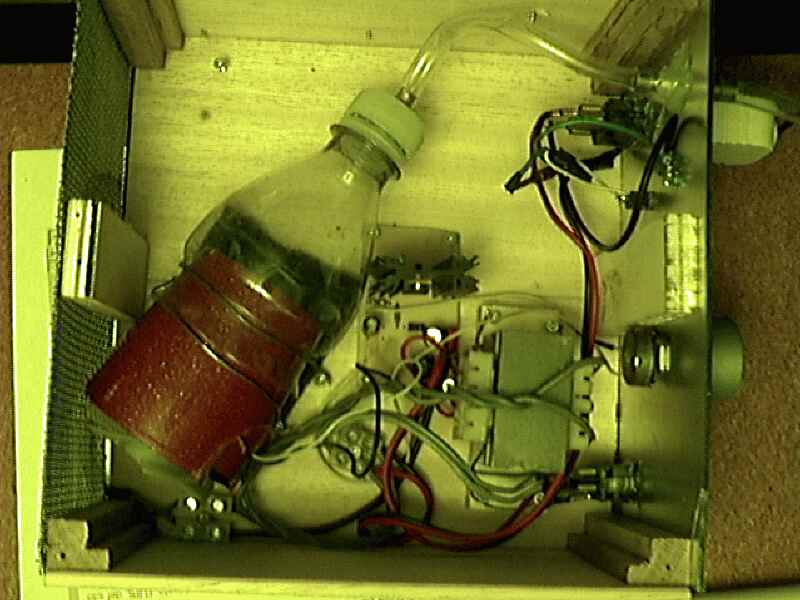
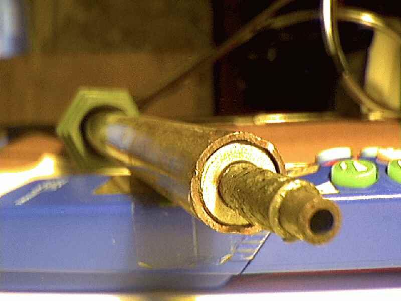
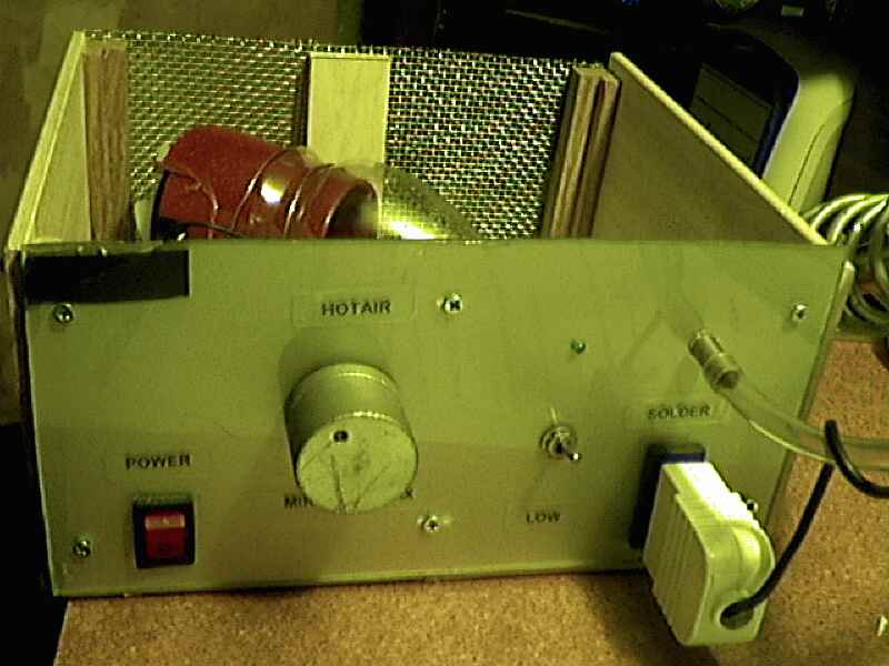
Working with SMT is quite
difficult without an smt hot air pencil. The prices of smt stations are
too high, so I decided to build it by my own, the result is very
impressive. Anyone with basics electronics can try to build it, it's
made with common materials. |

|
This project is a remote control system based on a pic and an universal remote controller for TV, named SIMPLEX. The IR signal of a specific remote controller is received from an IC receiver(SFH 505 or similar ) and sent to the pic, the inside program decodes the algorithm and switches 6 output ports and the corresponding relays .You can use it to control 6 appliances of your room such as lamp, radio, Hi-Fi , TV , computer and so on .The range is great about 10 meters Obviously you have to get the right remote controller , I used the above universal TV remote and programmed it with the 2242 code, it corresponds to the code of some Sony and Mitsubishi TV .I took the decoding algorithm from tanzilli.comand picpoint.com (they use a display which gives the numeric resulting code of the key pressed on the simplex) , if you want more search for "Simplex" keyword in these sites. The code that I've modified to switch six relays also let you test any remote control ir led , because there is a subroutine that beep the active piezo when you press any button . This last function is toggleable by switching on a particular channel (TV channel). Here is the code and the schematic .The final result is that you 'll be able to command all you room without moving a finger. I think that's wonderfull, Isn't it ? |


| Phone amplifier |
|
It's a useful 0.5 watt amplifier for phone line, powered by a simple 10 volt supply, it uses an isolated trasformer to get the sound from the telephone line and an audio transformer for the amplifier |

|
I think you
know what's a UIR so IF it isn't so go to TIES BOS page and learn
something :-) .! |
![]() Up
Up