Upgrading the Conrad Johnson Premier Fourteen preamp:
How much can influence the sound of a preamplifier one single resistor?
How much of the sound is due to the coupling capacitors?
How much can cost a good cap?
These and similar are the fundamental questions which motivated the tweaking described in this project.
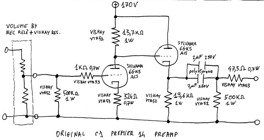
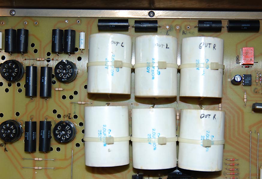
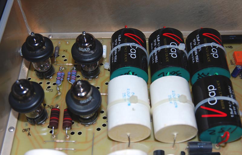
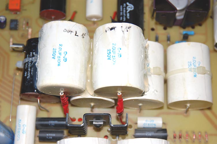
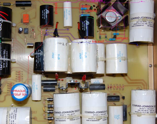
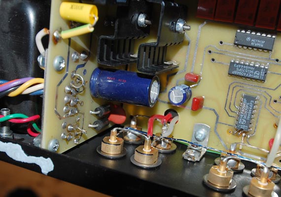
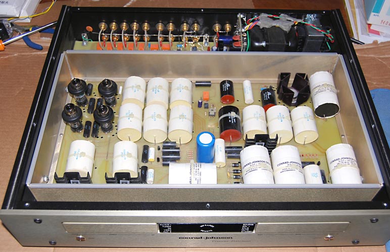
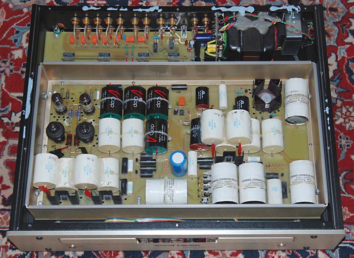
The Conrad-Johnson Premier Fourteen is a good preamplifier designed in 1995. As you can see from the picture above, there are many components inside, including a lot of polystyrene and polypropilene capacitors, but if you look to my hand made scheme below you will see that only a few of these parts are involved in the audio signal path. A part from the initial battery of Vishay resistors and Nec relé, implementing the volume attenuation, there are only 7 resistors, 2 triodes and 2 de-coupling caps per channel in the audio signal path. Note that at least 3 of the seven resistors are apparently not necessary (the two “loading” 500kOhm and the “output” 47.5 Ohm). In reality, there is also a small cap (510pF) in parallel with the 324 Ohm resistor, but I didn't draw it because you could think that it is a bypassing cap. Instead, it does not act like a bypass for the audio signal frequencies and it is there only to fight noise. So I ignored it. All the rest of the components inside the Premier Fourteen are used to implement the power supply, which consists in a main capacitor filter feeding two solid state regulated stages in cascade. The first, which is common for the two channels, ends with 2x2uF polystyrene caps, while the second is independent for each channel and ends with a single 2uF polystyrene cap.
|
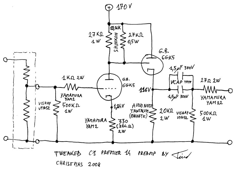
This is the Premier Fourteen signal scheme. |
|
I was told by a Canadian audio-friend that metal film resistor like the expensive Vishay used in my preamp does not sound so well as tantalum resistor (or at least resistors using tantalum in their junctions), in particular as intrinsic noise. So my first modification experiment was done to test if replacing some resistors could eventually change the sound.
 I
started my quest looking for the best tantalum resistors that I could
find. I was told that the best one were the Sfernice (France)
resistors, made under the Be Yamamura San design. These are no
more available (of course) and are very hard to find. With some help,
I was able to find some 2W YAM-SFER resistors with useful
values. This are double winded resistors (using bakelite cores?) to
be non-inductive and uses tantalum in their junctions. Of course,
they are amagnetic.
I
started my quest looking for the best tantalum resistors that I could
find. I was told that the best one were the Sfernice (France)
resistors, made under the Be Yamamura San design. These are no
more available (of course) and are very hard to find. With some help,
I was able to find some 2W YAM-SFER resistors with useful
values. This are double winded resistors (using bakelite cores?) to
be non-inductive and uses tantalum in their junctions. Of course,
they are amagnetic.
As second choice, I went for the out of production Shinkoh non-inductive resistors. I have fond some 1W, but not all that I needed, so I had to combine them with some Shinkoh 0.5W to cover the desired power.
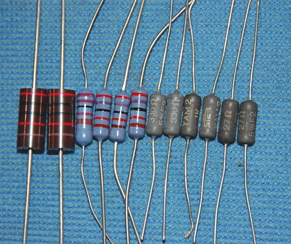
Finally, for what I was still missing, I went for the 2W Audio Note tantalum resistor (the first on the left side of the picture), but I discovered that these babies were the only one of the set which were responding to a magnetic field, so they are not amagnetic, and that is not very good...
In my quest, I contacted the following sources: Digitex (Firenze, Italy), HiFi-Collective ( UK), Borberly Audio ( DE), which here I thanks.
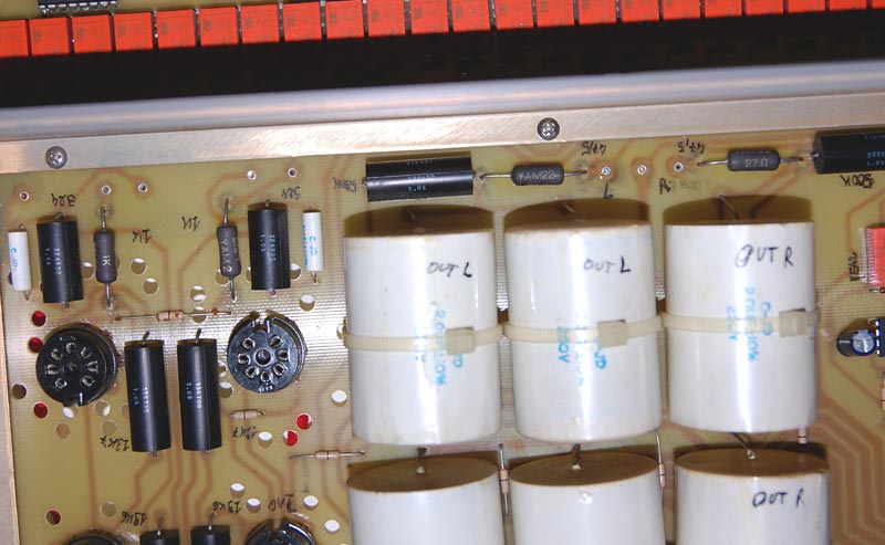
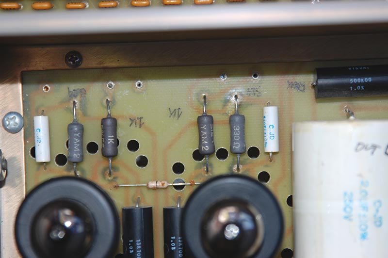
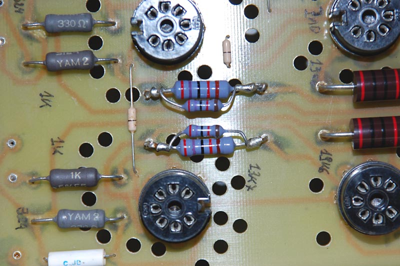
The first mod that I have implemented was to replace the two resistors in series with the audio signal. Since I was sceptic on the “sound of a resistor” religion, I thought that the resistors in series should be the best to test if there is or there isn't any such effect. So, in the stage 1, I replace the 1kOhm Vishay VTA53 0.7W (Bulk Metal Film resistor) bringing the signal on the grid of the first triode with a Yamamura YAM2 1kOhm 2W. At the same time, I also replaced the output 47.5 Ohm Vishay VTA53 0.7W with a Yamamura YAM22 27Ohm 2W. This is the only case were my replaced value is significantly different from the CJ original value. I thought that the only reason to exist of an “output” 47.5Ohm could be to prevent short cuts and that the exact value was not very critical. So, since I was not able to find a 47 Ohm Yamamura, I chose a 27 Ohm one, just to have a little lower preamp output impedance.
|
|
|
When I reconnected the preamp with these 4 different resistors I was blown away. I was not able to believe what a huge difference these four small resistors have made to the sound. The resolution and the feeling of transparency was greatly improved, giving a much more “modern” sound characteristic than before. Thinking back, I was really a stupid in replacing two resistors (per channel) at the same time, so I can't say which one of the two (the 1kOhm on the input grid or the 27Ohm on the output) was more responsible of the resolution improvement. My idea is that the 1kOhm was more important (even if the current going in the grid triode is extremely low), but I can't prove it. Also my wife was really surprised by the sound improvement. With this very simple mod I really was able to change the preamp “voice” to a more open one!
On the other side, in stage 2 I replaced the 324 Ohm Vishay VTA53 0.7W on the cathode of the first triode with a Yamamura YAM2 330 Ohm 2W, hand selected to measure 324 Ohm, without experiences similar dramatic changes. If there was any difference at all, it was still “on the same way” of a higher resolution and, maybe, of a drier bass.
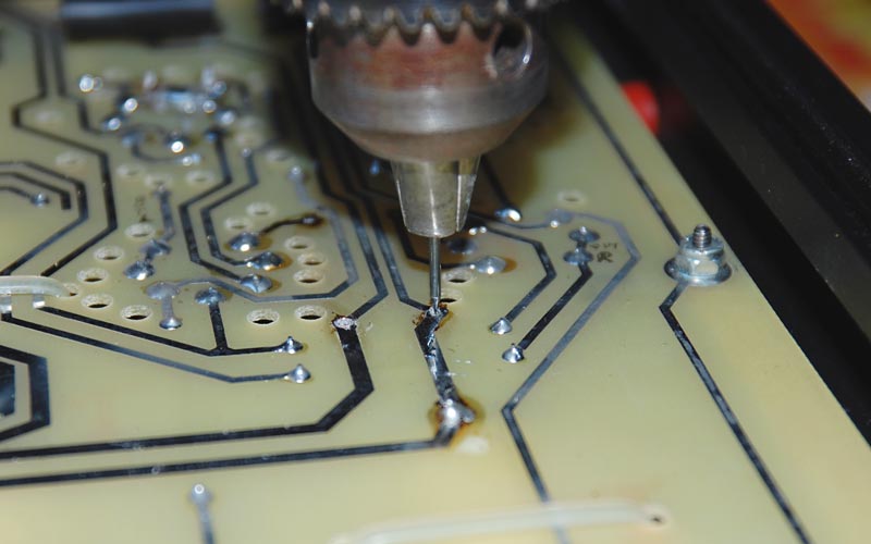
In stage 3 I replaced 19.6 kOhm Vishay VTA52 1W on the cathode of the output triode with a 20kOhm Audio Note tantalum 2W, without noting particular effects. Since the Audio Note have fatter legs, I had to drill a larger hole on the board...
|
|
|
|
|
|
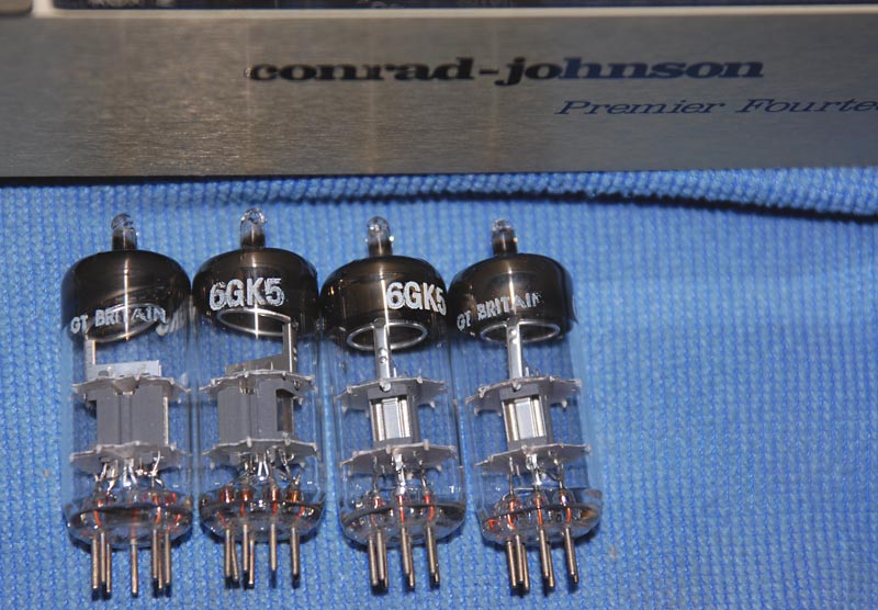
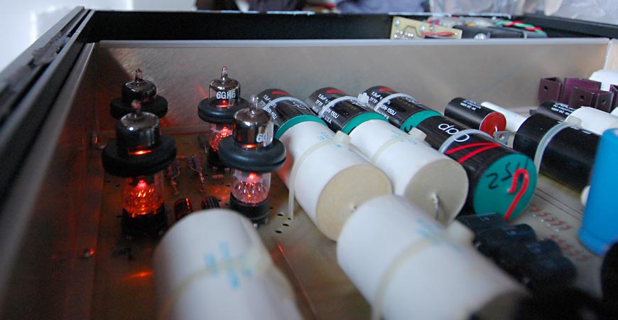
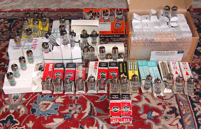
It was only at this point that I measured the high voltages (be very careful if you try to do something like that!) in the audio circuit and I understood that the 0.9V on the first triode cathode and 119V on its anode was indicating an almost exhausted tube. In stage 4 I then replaced the old Sylvania 6GK5 selected by Conrad-Johnson with four NOS 6GK5 “made in Gt Britain” (Mullard origin), and, of course, I had another big difference in the preamp sound, with larger soundstage and much richer harmonics. In the following times I made a lot of “tube rolling” to get the best performance and I ended with two Gt Britain 6GK5 as output triode, while I chose two NOS GE 6GK5 as input triode, because they were able to give me 1.3V on the cathode and 115V on the anode. The GE seem to have a higher noise background but also a better dynamic and bass presence than the etheric Gt Britain. BTW, I also updated the two Sylvania 6GK5 of my CJ DV-2b CD player with two CJ-selected GE 6GK5, because also the first were measuring 0.9V when used as input triode in my preamp, which became my favorite 6GK5 tester! As I said before, also stage 4 was a very audible improvement, similar to stage 1 as “audibility”.
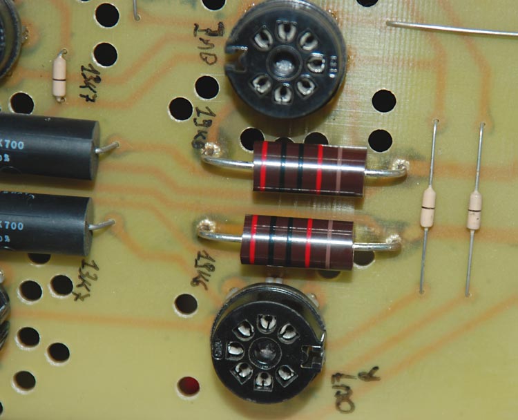
In stage 5 I replaced the 13.7kOhm Vishay VTA53 1W on the anode of the input triode with a parallel of two 27kOhm Shinkoh giving me a final 13.56kOhm value. HiFi Collective made a mistake in sending me the four 1W Shinkoh and after that discovered that they don't have any more of them, so here is where Erno Borberly come in help with his 0.5W Shinkoh. So in my parallel there is a 27kOhm 1W and a 27kOhm 0.5W. No audible difference to report.
In conclusion, when I replaced the resistors in series with the signal I heard a huge difference, while for the resistors on the cathode and anode the difference was not so huge, or was not able to sum with the previous. In comparison, with the original Vishay, the preamp voice was much more dark.
Then it came Christmas... and this year I was a very good boy!
|
|
|
|
|
|
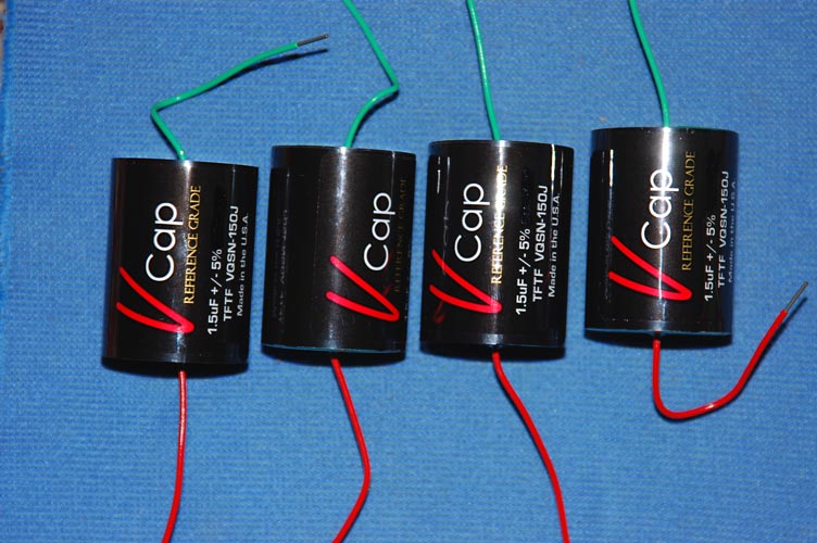
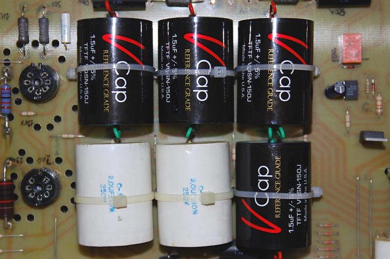
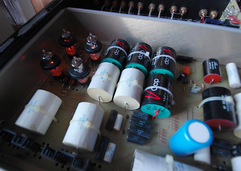
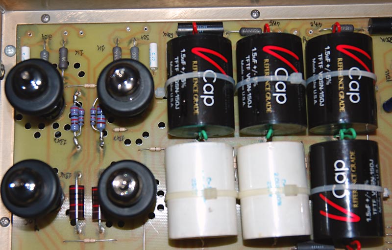
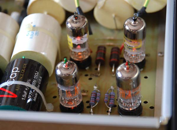
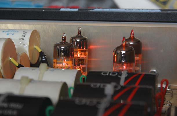
In fact, Santa Claus brought me four very expensive VCAP. You probably now that teflon's are considered the best audio capacitors ever made. Probably you also know that VCAP TFTF are considered to be the best Teflon caps (see for example the Tempo great capacitor shoot-out). What you probably don't know is how much they cost! If you buy a single 1.5uF 300V Vcap from Chris Venhaus VH-audio (North Prairie, WI, USA) on-line shop you are going to pay it about 250 US$. And I need 4 of them (2 in parallel for each channel)! More than that, I need four 2uF caps, not 1.5uF. I can tell you that I chose the 1.5uF values because their dimensions are identical to the original CJs 2uF to be replaced, or that I evaluated that the low-pass cut off will not change significantly with a total of 3uF instead of 4uF (consider a loading impedance of about 80kOhm) but you are right if you think that I have bought the 1.5uF only because they are cheaper than the 2uF (252$ vs. 322$, check http://www.v-cap.com/tefloncapacitors.html)!
That was a difficult decision: it is worth to spend 1k$ to upgrade the output caps of your preamp?
I asked to Chris if I can replace only one of the two output cap in the parallel but he answered that I will have problem with different timing in the two caps and that will introduce distorsion. I asked if I can simply parallel the original 2+2uF with a 1/10 Vcap and he told me that it is not very effective, and that in such case he suggests only a 1/100 value. At the end he convinced me to try the “right mod”. In some way, I sacrifyed myself to answer the above question and let you know, so consider yourself as an active part of this drama.
|
|
|
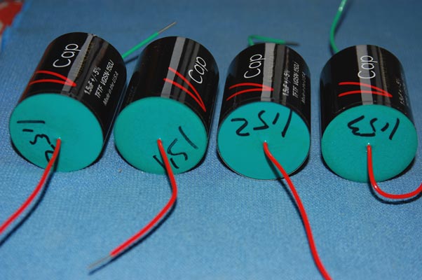
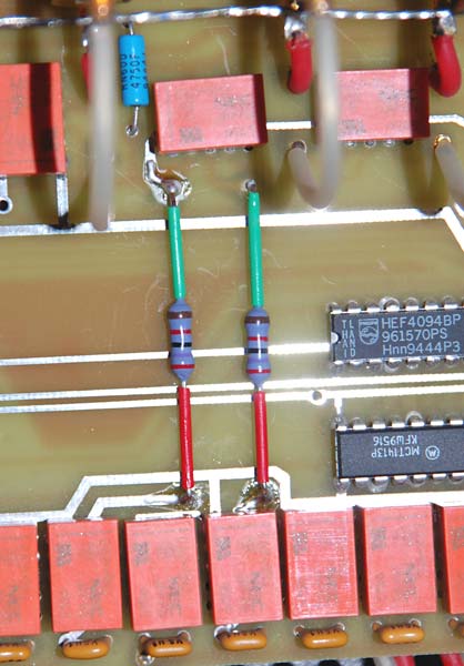
I connected the “outer foil” (green terminal) of each cap toward the lower impedance side, which is the 6GK5 cathode and then... let them burn!
TA-DAAA!
Yes! It is worth to spend 1k$ to upgrade the output caps to the highest teflon level!
At the begging you are transposed by the additional details that you can listen in every record. The sound is very different. The voice of my CJ Premier Fourteen was completely different after this modification. At the begging, I simply wondered if I liked its “new voice”. Extra detailed, super speed (transient were never so fast), but a little... cold. Only much time after I understood that it was probably a problem of break-in. After some 50 hours of burn-in the “main sound” of these cap is there, but it will take a very long time to stabilize it in the definitive form. I think that 1000h of use are a true time period to finally judge the many improvements obtained by these Vcap.
|
|
|
Of course, I didn't expect so much, and my initial judge was that, yes, my new Premier Fourteen (let's call it TEA 14, since it has a completely different sound) had a much higher resolution and level of transparency (already higher after the resistors mod, but even more adding the four Vcap) and also was much faster and with more dynamic and precise soundstage, but... I was missing that “warm” bass that characterized (now I understand) the original version. So, what can I do to improve a little the bass response?
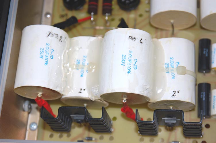
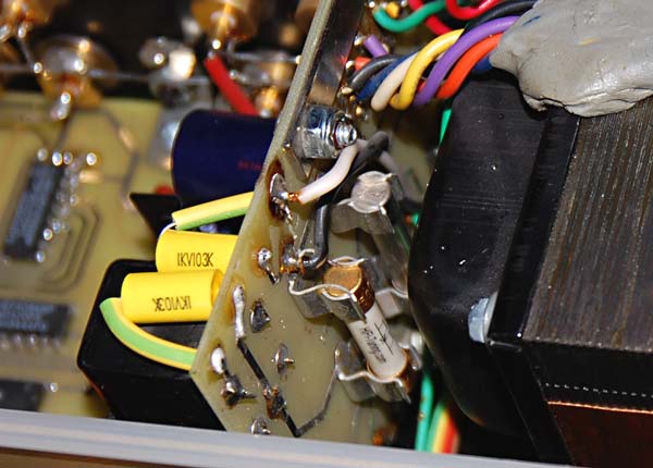
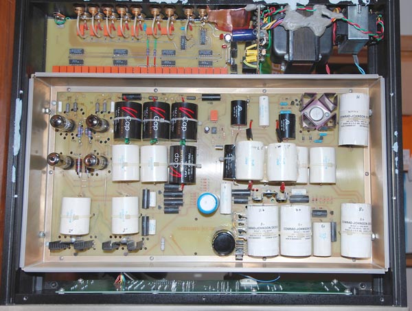
Instead of waiting the full Vcap break-in, I started reasoning on the regulated power supply. I had in my dirty hands 4x2uF 250V CJ polystyrene caps, so, why don't reuse them? I decided to double the capacitors at the output of the power supply. I added 2x2uF to the output of the first power supply, where two similar caps where already doing their service. Lastly, I added a 2uF polystyrene cap to each of the second stage supply outputs (one per channel), where a similar 2uF cap was already present.
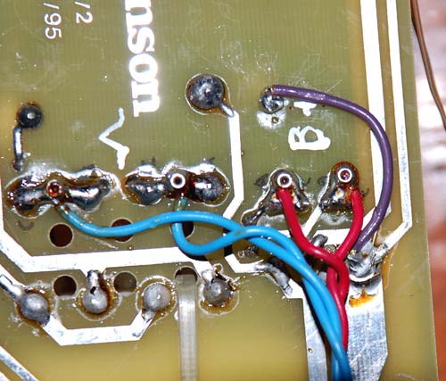
Then? Well, the bass was stronger, yes. Probably because of the lower impedance obtained doubling the output caps. An expert told me that I was risking to overload the solid state regulators involved in these circuits, so if you are going to follow my steps here you are advised about the risk. After many trials, I decided that the single cap on the output of the second stage regulator was providing a stronger bass, but in some way it was also acting on the highs, which was not so shining as before. At the end I desoldered these two caps (visible on the left picture below with the red Cardas 15AWG wire). Note that I have note found any reasonable explanation why doubling the 2uF polystyrene cap in the final output of the B+ supply (working at about 170V) could make the highs a little “dirty”. Maybe it could be a problem of the connections involved and their topology. I accepted the response of my ears and trusted them. So I'm still wondering where to place these two spared caps and probably I will put them on the initial filtering cap bank (where there are already 4x30uF polyprolpylene capacitors) or on the tube heather (filament) supply, where there is another 30uF polyprolpylene cap. How you can see, there is some work in progress and I will update this page in future.
|
|
|
The picture below summarize the work done on the audio signal circuit, while for what concern the work on the power supply, it is not already finished. Comparing this circuit with the original drawn above you can see that the electrical parts are all (but the output 27 Ohm resistors) equivalent. For my engineers friends who states that “only the scheme matters” and not the “exotic parts”, I invite them to listen my modified preamp and they will surely agree that it is much better now than before.
|
|
|
As a first conclusion, I would say that the resistors replacement was not too much expensive, but very worth of (given that you are able to find Yamamura or Shinkoh resistors). Note that the original Vishay Bulk Metal Foil VTA52 and 53 are considered very well among the audiophile community (even if not so well as the top Vishay Z201 series, see this interesting diyaudio post), but still I think that the Yamamura's in particular sound much better. Every world has its own saints. I think that Hi-End world can tribute the honour to become a saint to Be Yamamura San! And Chris Venhaus is on the road to Hi-End sanctity as well, he have just to release a cheaper version of his teflon caps! Next year, if I will still have my CJ MV60SE power amp (because its main power transformer is excessively buzzing), I already know what I will ask to Santa Claus!
BTW, do you know how much does it cost the cheapest Conrad-Johnson preamp with Teflon caps? In Italy it is listed at 12.5kEuro. I'm not saying that with these upgrades you will transform a Premier 14 in a CT5, but simply that you will improve a lot its performance. More, if you really like the sound of your Premier 14, then I suggest you not to implement these mods, even not the simple resistors replacement, because the “voice” of your beloved Premier 14 will be changed.
With the new resistors and Vcaps (and with 8 polystyrene microfarad instead than 4uF on the output of the first regulator power stage) my old Premier Fourteen received a second life: much more resolution, higher speed, more focused but also wide soundstage and probably a clearer bass response. Of course, to appreciate it (and to justify the expense and time spent) you need a system which is at a similar level and in particular which is quite resolving. I wish I had on hand the good amps (the Kronzilla in primis) that I have tested last year for a “follow up” with this better preamp... but, alash, my wife would kill me! I'm already lucky that I did most of this work before to test the magic My Sonic combo (see my reportage here)!
Phase two:
Can a fuse sound?
Can a diode sound?
Can static electricity ruins good sound?
These questions motivate the pursuit of improving the CJ Premier Fourteen – TEA version toward new upper limits.
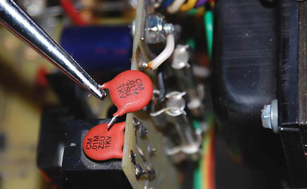
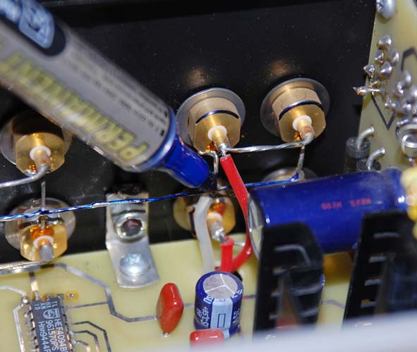
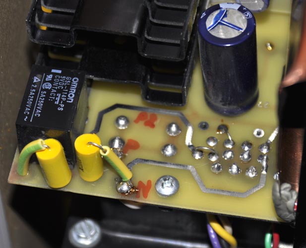
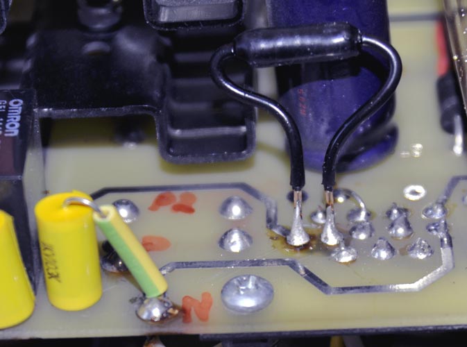
First, of all, one day, while working on the running preamp, I have discovered that a disc capacitor used near the Omron AC filter was literally “ringing”. Since I was told that disc caps are “horrible devices” I replaced two of them with equivalent (10nF 1kV) radial polystyrene capacitors (ICEL) and the ringing disappeared. These caps are close to the two fuses, so, what a better opportunity to replace the tube circuit fuse with an expensive Hi-Fi Tuning ceramic-Ag (golden plated) fuse? The type used is a 500mA slow blow 3AG (6.3x32mm), which I have bought from Elite Diffusion (France) at 22 Euro plus shipping. As many other audiophiles has already found, also I was able to listen difference when using this fuse instead of the original Littelfuse 313, in particular in the mid-highs frequency, which become more... “clear and shining”.
|
|
|
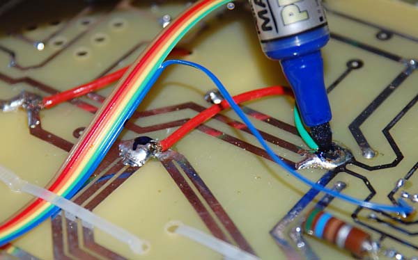
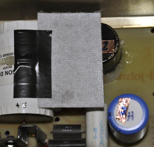
To the risk of appear insane, I decided to try also the antistatic tools that my friend Faber has recently developed and in particular I used the Faber's Magic Marker, which is able to draw an antistatic liquid. I used it on the edges of the transformers, fuses, RCA female sockets and on the common ground wire and star points. Apparently, it was able to increase the scene and details, as I have found that it can do also when used simply to mark a small sign on the CDs or even on the LP labels!
|
|
|
|---|
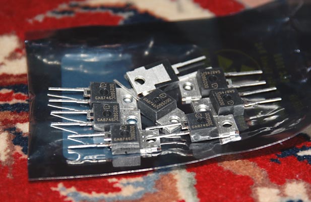
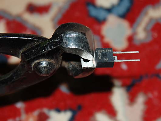
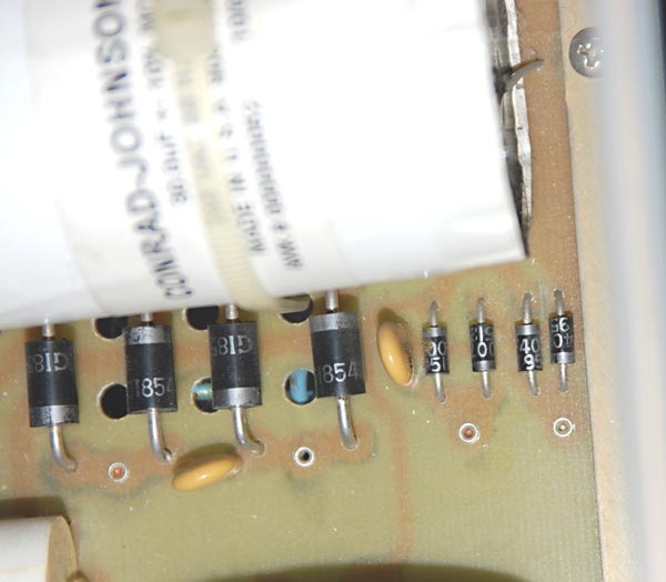
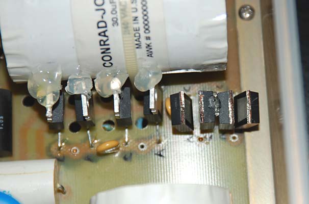
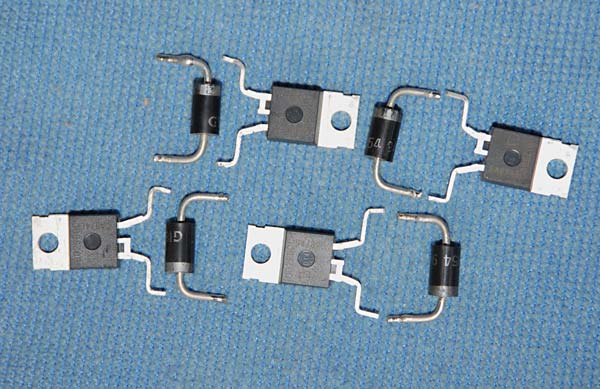
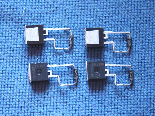
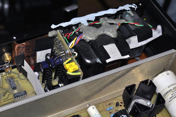
After discovering the sound of a fuse, why not believe what my audio friend Rocco was saying about the sound of diodes? Why not try to improve also the rectification bridge diodes? After many research he has found that the best rectifying diode specs are those of the Infineon IDT02S60C 2A Schottky rectifier, which you can find here. I used four IDT02S60C to replace the bridge previously made with GI854 in the heather (filament) supply and other four to replace the uF4007 in the main (B+) supply. In both cases I had to work a little to adapt the TO-220 case legs to the original CJ board holes, and I also had to fix their position with hot glue...but the work was much worth of. In fact, these diodes were able to release a much more dynamic and powerful sound, which you can note in particular on the bass frequencies. I think that the replacement of the heather supply diodes was a particularly important improvement and was able to equilibrate the goodness of the full spectrum, which was gone a little toward the bright side. But also the B+ diodes were able to improve the perception of energy associated with very low frequencies.
After all that work, what to do more?
Remembering the differences that I have noted when trying different 6GK5 tubes (GE, UK, Sylvania,...) I decided to play more “tube rolling”, in particular with a brand of tubes which I didn't try before: the RCA, which Joe Levy (Tempo Audio) thinks are the best 6GK5 ever made. After buying some more 6GK5 on eBay (including RCA, Raytheon, Magnavox, Realistic Lifetime,...and including 6FQ5A, which I guess is an exact replacement for 6GK5, even if datasheets suggest a typical grid voltage of -1.0 for 6GK5 and of -1.2V for 6FQ5A) I decided to buy two old-logo RCA 6GK5 “MC” hyperselection by Andy Bowman (http://vintagetubeservices.com), the man who transformed tube selection in an -expensive-”art”. I have now about 70 samples of 6GK5 and I think that none of them sounds so well as the two Andy's RCA put on the input stage (the two 6GK5 closer to the back of the preamp). The only defect that I can find is that they are a little too “sweet” and that the cathode voltage, after only a few hours of use, has dropped to about 1.17V, which means that their expected life is not so long as their price should guarantee. In fact, in my experience, when a 6GK5 is like new, the cathode voltage in this preamp scheme is as high as 1.32V. When it has been used a little it is still above 1.2V, while, when it has been used a lot, it is about 1.1V. Finally, if the 6GK5 is exhausted, then the cathode voltage will be less than 1.0V. Note that these values are referred having about 12.4V on the heater supply, which are divided on the two triodes of each channel, connected in series. If these tubes are not equals, you will not have the expected 6.2V on the filament. For example, after only two weeks of use, one of the two Andy's RCA dropped his cathode voltage to only 1.11V and its heater voltage to only 5.7V (given to a probably a lowered filament resistance) and both are synonymous of a weak tube. I sent them back and asked Andy for a replacement, but the two RCA new logo that he sent me after many moths were even worse (one had a dangerously low heather resistance) so I can't suggest him as a reliable source, at least for the 6GK5 tubes.
|
|
|
|
|
|
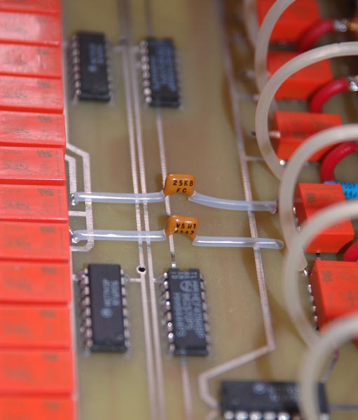
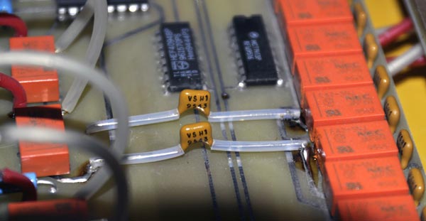
The CJ Premier Fourteen preamp has 25dB of maximum gain, which I believe are too much when using it with a CD player or a phono which has also an additional gain provided by a MC transformer. In fact, in our system my wife usually set the gain in the 10-20 range, while I prefer the 20-30 volume range. Only when I have some audiophile meeting (and my wife is not at home) I set higher volumes, in the 40-50 range. Note that I use the preamplifier always to attenuate the incoming signal, since the preamp output will be equal to the input when the volume is set to about 60 and I never do that! So, I think that the 99 steps implemented by the CJ relé-based logic (controlling a set of 12 Vishay VS H1 resistors per channel) are not well calibrated. Then, I decided to decrease the total gain of this unit, in order to use higher volume sets. Since I didn't want to change the working point of the first 6GK5 (to decrease the amplification factor), the only other option which I have found was to increase the first input impedance, which is used in the volume voltage partitioning.
To increase the total input impedance could be problematic if you are using highly inductive cables, since they are forming a low-pass filter. The original CJ input resistor was a Vishay VS H1 25.8 kOhm, at which is added the resistance chosen by the relé (varying with the volume set). Since I discovered that there are hi-end preamps, like the Audio Note M8, which have 100 kOhm of input impedance, I thought that 43 kOhm could be a safe replacement. So, I removed the Vishay VS H1 25.8 k and put a Shinkoh tantalum 43 kOhm resistor. In such a way, I measured a decrease in gain of about -4.3 dB, corresponding to about 6 steps of volume, since each unit of volume is 0.7 dB. My wife appreciated it very much. Unfortunately, the days after, I had the feeling that the highs were not so shining and alive as before. To test this point, I tried to replace the 43kOhm Shinkoh with a 27 kOhm Shinkoh and immediately the highs were shining again, despite the bad weather outside. I don't know why a 43k input impedance created these problems, but that is what my ears said, and I trust them!
|
|
|
 Was
all that worth of?
Was
all that worth of?
Well, it is not an easy question. When I started it I didn't know how long and expensive (also in terms of time-consuming and Wife-Irritation Factor) this project would be. Also, usually hi-fi gears are “voiced” to reach a desired equilibrium. When you touch something (as the initially the resistors), you alter that equilibrium and, even if you are actually improving something, you will probably not be completely satisfied until you can reach a new equilibrium point. For example, doubling some polystyrene caps in the power supply and upgrading the diodes were able to improve the mid-bass region and the dynamic as much as the high frequencies and resolution were improved by other mods (like resistors, Vcaps and fuse). In such a way, the final result is not only better than the original in many parameters, but it is still “well equilibrated”. For example, I asked to my friend George Gloomy to listen my system and to tell me which defects he can find. Well, he told me that the music was so pleasing (clear and well resolved, but still sweet) that he was really not able to concentrate on any defects at all...
Many DIY-ers states that their projects are far superior to the commercial products that you can buy at “human” prices, because they can use very good and vintage parts, which companies can't use, because they are not available in big quantities or because they are too expensive (consider that a company usually multiply by 10 the original costs of parts to find the commercial price of their products). I don't know how good in absolute terms my CJ-TEA Premier Fourteen became (I would like to compare it with some good CJ Act or Zanden preamp to discover it), but I'm sure that if I add to the value of my old Premier Fourteen on the 2nd hand market (about 2kE) what I have spent for all these upgrades (about 1.5kE, without my work, of course) I will obtain a value with which I guess that I can't buy something as good as my CJ-TEA 14. Remember that in Italy the cheapest CJ preamp which has Teflon caps inside costs 12.5kE!
 The
only other drawback which I had with this project is that the more
I improved my preamp, the more the analogue was sounding better than
the digital source. I tried to improve my CJ DV-2b CD-player with
a HiFi Tuning fuse (1A fast blow) and adding inside a Stillpoints ERS
anti-EMI cloth and both mods helped, but the sound coming from my
vinyls was always much more “realistic” than that coming
from my CDs...
The
only other drawback which I had with this project is that the more
I improved my preamp, the more the analogue was sounding better than
the digital source. I tried to improve my CJ DV-2b CD-player with
a HiFi Tuning fuse (1A fast blow) and adding inside a Stillpoints ERS
anti-EMI cloth and both mods helped, but the sound coming from my
vinyls was always much more “realistic” than that coming
from my CDs...
I finished soldering the last -volume- resistor on 25 March 2009. Then I decided to celebrate listening some good music. Since we were close to Easter, I choose the Bach Passion. If you look on my list of favourites records you will find the John Passion with Sigiswald Kuijken and the Petite Band (EMI-DHM), but since my daughter is called Mateja, I wanted to listen the Matthew Passion. And so, I just discovered that Kuijken has not yet recorded the Matthew Passion! What to do?
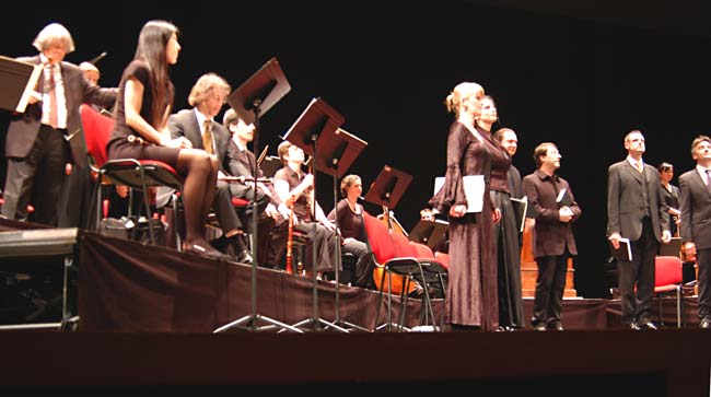
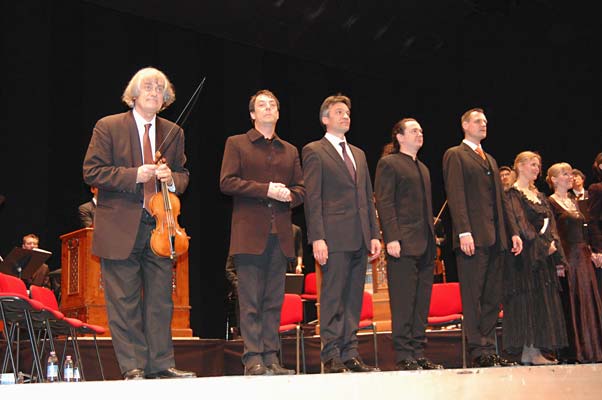
Well, the only other option was to drive 50 km to the city of Udine, where Sigiswald Kuijken and his Petite Band (11 instruments on each of the 2 orchestra plus 11 singers) were performing the Bach Matthew Passion. Buying the tickets at the last moment I finished in the third raw (just in front of the first orchestra), but moved to the first raw during the second part of the long performance (at about 7m far from Sigiswald playing the violin and also a beautiful viola da gamba). What to say? Unfortunately there were no tubes in the “signal path”, but the sound was really exciting, all the same!
|
|
|
Lastly I would like to thank all the guys who, in a matter or the other, helped to realize this project (the order is not important!):
Rocco Bortone (Canada)
Chris Venhaus http://www.v-cap.com
Mateja Manzato (Italy)
Erno Borbely http://www.borbelyaudio.com
Bill Thanemann http://www.musictechnology.com
Claudio Certini (Firenze) http://www.digitex.it
Joe Levy http://www.tempoelectric.com
Andy Bowman http://vintagetubeservices.com
Mihaela Kavcic (Slovenia)
Fabio Zanco (Conegliano) http://www.elcoteam.com
Livio Stefanuto (Italy)
Phase three: adding some Black Magic
How much bad is the supply noise?
How much sensitive to noise is the tube heater circuit?
How much magic are the Black Gate capacitors?
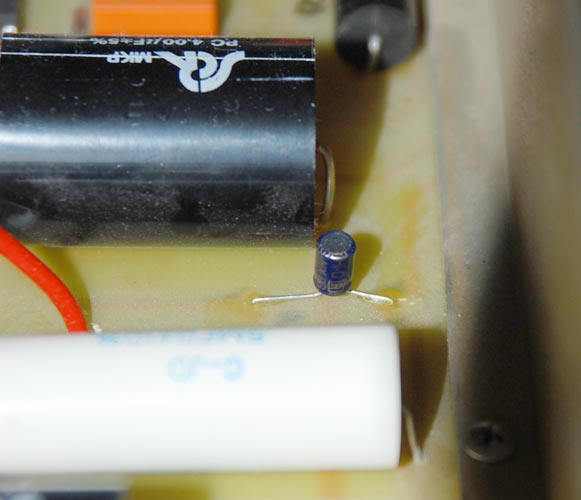
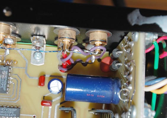
While I was satisfied by my actual version of the CJ-TEA Premier 14, my friend Rocco insisted that the heater supply must be as clean as possible. CJ designed a 12.6 DC voltage supply for the 6GK5 heaters (filaments), since they are connected in series for each channel. After the four Infineon rectifiers there is a 4700uF 50V Sprague electrolytic capacitor, bypassed by a CJ 0.5uF polystyrene cap and by another SCR MKP 4uF polypropylene cap. At this point I connected a Black Gate NX Hi-Q 0.47uF 50V “electron transfer” non-polarized capacitor just across the Sprague pins. The Black Gate NX series become famous as a “noise drainer” capacitor, so that it is often used to bypass larger (and noisier) electrolytics. After this first levelling block there is a first active stage, followed by a Zener diode in parallel with another SCR MKP 4uF cap. Since the Zener is also a noisy component, I put another Black Gate NX Hi-Q 0.10uF 50V cap across its leags. Then this voltage of about 13.7V is used as input of a BJT Darlingthon stage, at which output there are about 12.5V, levelled by a CJ 30uF 450V polypropylene cap, bypassed by a 0.5uF polystyrene cap. Also at this point I added a third Black Gate NX Hi-Q 0.10uF 50V cap.
|
|
|
|
|
|
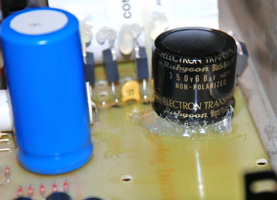
After that work on the heater supply I can't leave the B+ (tube circuit) supply without any Black Gate Magic. So I bought one of the very famous (and hard to find) Rubycon-Black Gate NH 68uF 350V non-polarized electron transfer capacitor to be used just after the Infineon rectifiers. Since I was not able to find a good place for this cap, I decided to remove one of the original four CJ 30uF 450V capacitors used to level the B+ input (which are bypassed by a 0.5uF polystyrene cap). In such a way I was able to put this cap very close to the diodes adding only a short cable. The total capacitance increase from 120uF to 158uF.
|
|
|
I made all this mods all together, so I can't evaluate the changes due to each of the four added caps, but I suspect that the big improvement in “speed” (now the slew rate is more typical for a SS preamp than for a tube one!), clearness and power is more due to the NH 68uF than to the NX small caps. If it is so, the BG NH 68uF 350V could be one of the best parts (as quality/price) ever build in the Hi-Fi market. It is really a pity that it is no more in production!
Never ending upgrades:
|
|
|
|
|
|
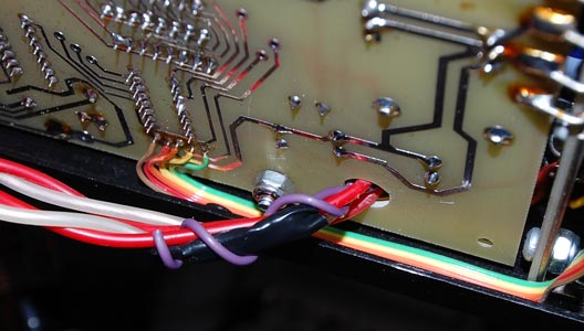
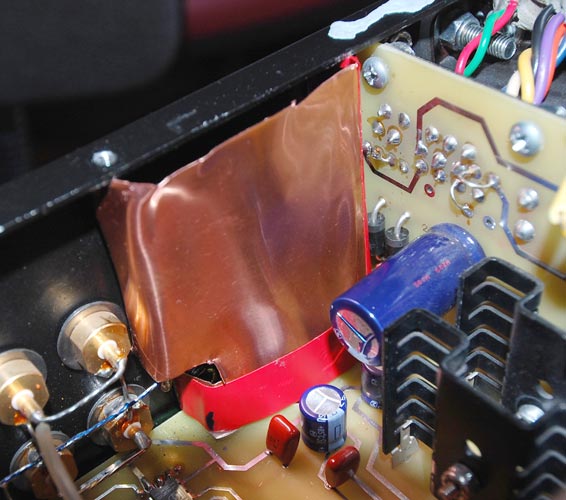
Finally I tried to decrease the noise which I always had on the right channel and have prolonged one of the output ground shielding wire and have built a copper shield around the output sockets, but without any success in decreasing the right channel noise. So, you see that I have not yet finished my work in progress!
Tino © January-March 2009
Phase four: updating to the most modern Black Magic
If you think that you have already read everything about audio-voodoo, then prepare to be surprised!
In the last twoyear I have read a lot of buzzing about the Bybee quantum purifiers. After a lot of doubts I finally tested them inside my highly modded Sony XA5400ES. (in series with the AC neutral and phase wires) finding incredible results. So I wanted to install one of them also in my Premier Fourteen. But that time I bought a golden Bybee, which is extremely expensive. I installed it just before the main power transformer input (primary), that is, after the HiFi Tuning fuse and the Omron relé.
|
|
|
This mod was simply astonishing. I can't write more because I have not yet finished the recommended 100h of break-in (it has only a few days), but the sound is already improved to a further level.
Working again inside the preamp, I decided to add also a little of Stillpoints ERS cloth, to shield aagainst EMI/RFI noise.
|
|
|
I was not able to judge the effect of the ERS, because the difference introduced by the golden Bybee was already enormous.
Lastly, I was told that the 25.8kOhm input Vishay H1 resistors that I replaced with the two Shinkoh are among the best resistors ever produced by Vishay. So, since the other volume resistors are still Vishay H1, I decided to reinstall the two original 25.8k VS H1.
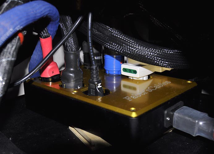
The
day before these last upgrades I have bought a wonderful FaberSix
power plant distributors (9 kg of drilled solid aluminium!) with a
new Faber's Cables power
cord Level 2. These upgrades together with the golden Bybee installed
inside the CJ-TEA preamp were really able to launch my system in
orbit!
Well, what to say more? Long life to the CJ Premier Fourteen!
Tino © January 2011